
Home - Search - Browse - Alphabetic Index: 0- 1- 2- 3- 4- 5- 6- 7- 8- 9
A- B- C- D- E- F- G- H- I- J- K- L- M- N- O- P- Q- R- S- T- U- V- W- X- Y- Z
Soyuz 7K-LOK
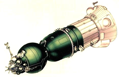
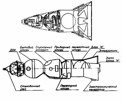
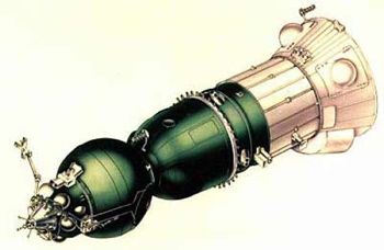
 LOK Cutaway Credit: © Mark Wade |
AKA: 11F93;7K-LOK;LOK;LOK, T1K;T1K. Status: Operational 1971. First Launch: 1971-06-26. Last Launch: 1972-11-23. Number: 2 . Thrust: 33.22 kN (7,469 lbf). Gross mass: 9,850 kg (21,710 lb). Unfuelled mass: 6,698 kg (14,766 lb). Specific impulse: 314 s. Height: 10.06 m (33.00 ft).
Given its importance to the Soviet moon landing program, it remains one of the least known manned spacecraft ever to reach flight status. Never reaching space in its all-up form, the LOK was the counterpart to the American CSM (Command-Service Module).
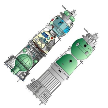
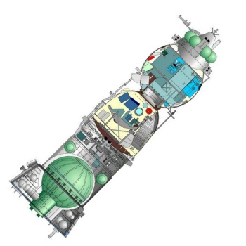
The LOK was radically different from other spacecraft in the Soyuz series in many respects. The BO orbital module differed from the basic Soyuz in having the Kontakt lightweight docking system, a forward reaction control system module, and a cupola allowing the cosmonaut to make a manual visual docking with the LK lunar lander. The descent module was true to the basic Soyuz form, but significantly heavier than either the 7K-OK earth orbit or 7K-L1 circumlunar versions of the module. The PO/AO service module was radically different from others in the Soyuz series. It featured the Block I propulsion system with a much more powerful engine and greater fuel capacity (required for the maneuver out of lunar orbit). Power was provided by Lox/LH2 fuel cells, a first for a Soviet spacecraft.
Development History - from L-4 to LOK
The first outline specification for a manned lunar orbiter came in a Korolev letter to the Central Committee of the Communist Part in January 1960. The Chief Designer proposed an aggressive program for Communist conquest of space. This would be accomplished by development of a new N1 rocket of 1,000 to 2,000 metric tons gross lift-off mass with a 60 to 80 metric ton payload at the earliest possible date. Among the potential payloads for his rocket in the period 1963 to 1965 Korolev proposed a spacecraft with 2 to 3 men for flyby of the moon, entry into lunar orbit, and return to earth. Payload mass would be 10 to 12 metric tons in lunar orbit with 2 to 3 metric tons return payload. This lunar orbiter would be twice as large as the L1 'loop around the moon' spacecraft. Following negotiations with other Chief Designers and the government, the final decree 715-296 of 23 June 1960 authorized draft project work on the L1 and the N1 booster but did not mention any N1-launched lunar orbiter.
Following three years of design and research, a series of potential lunar spacecraft designs were described in a 23 September 1963 letter setting out Korolev's space exploration plan for 1965 to 1975. One of these, the L-4 Manned Lunar Orbiter Research Spacecraft would have taken two to three cosmonauts into lunar orbit for an extended survey and mapping mission. The L-4 complex, with a total mass of 75 tonnes, would be placed into orbit in a single N1 launch, and would consist of:
- The trans-lunar injection stage, total mass 58 tonnes. If development of a fourth stage for the N1 was not authorized, this could be replaced by three sequentially-fired Soyuz B 9KM rocket blocks developed for the L-1 and L-2 projects.
- The lunar orbit maneuvering stage, which would have a total mass of 11.5 tonnes. This would break the Soyuz manned spacecraft into lunar orbit and returned it on its transearth trajectory. Five tonnes of propellant would be used for lunar orbit insertion.
- The L-4 spacecraft, which would be a modification of the 7K Soyuz. This would have a mass of 5.5 tonnes after being placed on a transearth trajectory with a descent capsule mass of 2.5 tonnes.
At the time of this proposal Korolev favored an earth-orbit rendezvous method to reach the moon. This would require several N1 launches to assemble a 200 tonne spacecraft in low earth orbit. This would be launched directly to the lunar surface.
In August 1964 the Soviet Union finally decided to attempt to land a man on the moon before the United States. Korolev took the decision to use the American lunar orbit rendezvous method to reduce the number of N1 launches from three to one. The design work already accomplished on the L4 came in handy to provide a counterpart to the American Apollo CSM. Unlike the CSM, the Soviet LK lunar lander and LOK lunar orbiter would be braked into lunar orbit by a separate stage, the Block D. Therefore the propulsion system of the LOK would be needed only for the critical maneuver of propelling the spacecraft on the return trip for lunar orbit toward the earth. The LOK would have a smaller Block I propulsion stage than that planned for the L4:
- Main Propulsion Stage: 11,500 kg (L4) vs 5,646 kg (LOK)
- Jettisonable Equipment Modules: 3,000 kg (L4) vs 1,400 kg (LOK)
- Re-entry Capsule: 2,500 kg (L4) vs 2,804 kg (LOK)
Technical description of the LOK
The design mission of the LOK was house the mission crew and provide a means of escape during the trip to lunar orbit, to rendezvous and dock with the LK after its return from the lunar surface, and then return the cosmonauts and their lunar samples to earth. On precursor manned and unmanned missions the LOK would be equipped with photographic equipment to survey potential lunar landing sites. The LOK had an overall length of 10.0 m, a diameter of 2.2 m, and a total mass of 9,850 kg. It was designed to support two cosmonauts on lunar orbital missions of up to 13 days duration.
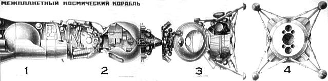
The LOK consisted of the following modules, from fore to aft:
- SU (Stikovochniy Uzel) - Docking apparatus. This was a truncated cone, 455 mm long, topped by three probes that would snare the hexagonal grid atop the LK. A mechanical turn-screw brought the probes out into a splayed position to lock the two spacecraft together. This lightweight device allowed firm connection of the spacecraft without the requirement for a precision aligned docking. It formed part of the Kontakt docking system designed by Mnatsakian at the NII for Precision Instruments.
- DOK (Dvigateliy Orbitalniy Kompleks) - Orbital engine system. This provided orientation for the LOK during trans-lunar coast and lunar orbit operations. This module, a 790 mm long truncated cone pierced by spherical propellant tanks, was developed by KB Arsenal, Leningrad. Work was concurrent with their productionization of similar maneuvering engine systems for the IS and US maneuverable anti-satellite and anti-ship systems. The module had a total mass of 800 kg, including 300 kg of propellant in six spherical tanks. These were fed by four smaller pressurization tanks to four clusters of thrusters with a total of 24 engines. Two of the clusters consisted of a pair of larger forward-firing translation nozzles, a pair of larger aft-firing translation nozzles canted at about 40 degrees from the vertical, and a single pair of smaller perpendicularly-firing yaw engines. The other two clusters consisted of a pair of smaller perpendicularly-firing pitch engines and two pairs of even smaller tangentially-firing roll engines. The propellant would provide about 90,000 kgf-sec of orientation impulse, which is consistent with the 360,000 kgf-sec provided by the RCS system of the much larger Apollo spacecraft.
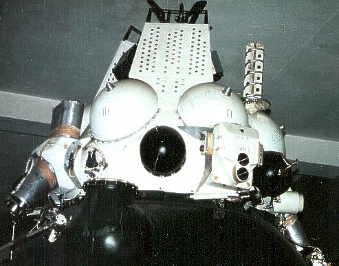
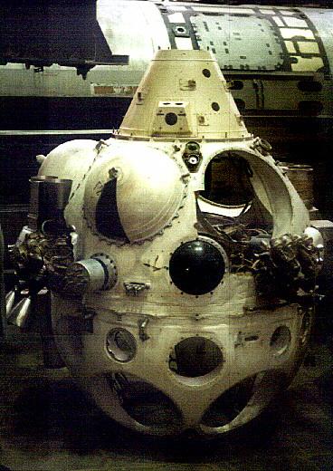
- BO (Bitovoy Otsek) - Living compartment. This was similar to the basic Soyuz, with several important changes. Not a simple sphere or sphere-and-cylinder, it consisted of a forward hemisphere 885 mm long with a radius of 1085 mm, a 236 mm transition, and an 1114 mm long aft hemisphere of 1143 mm radius. In the forward hemisphere a cupola was installed, allowing the cosmonaut a direct forward view in order to make a manual visual docking with the LK lunar lander. It was equipped with the highly classified laser-optical system designed by NPO Geofizika for the Kontakt docking system. As in other Soyuz spacecraft, the BO served as a living area, experimental laboratory, and airlock for EVA operations. A hatch at the base of the module sealed the cabin off from the SA descent module, while a hatch in the lower hemisphere allowed the cosmonauts to exit into space.
In coming up into the BO from the SA, the cosmonaut first went through a short tunnel leading to the 'floor' of the BO. A cosmonaut floating above the tunnel and facing the hatch would find:
- To his front, the hatch leading to free space in the lower part of the compartment.
- To his left, the main console of the compartment, a vertical wall filling about 40% of the cabin. The lower areas were devoid of instrumentation but housed the environmental control system, pressurization/depressurization system, and storage lockers for food, water, and the Orlan space suit for the crew member to remain aboard the LOK. In the upper panel were instruments for monitoring the LOK during cabin operations and when it was depressurized. This included a blue console with strip pressure indicators, a clock and timer, standard Soviet sequencer controls to command and track automated sequences for spacecraft operations, and communications controls. A dark green console provided master toggle switches to activate or deactivate LOK systems. At the top of the console a lattice structure protected plumbing and provided additional stowage.
- Behind the cosmonaut, were an array of specialized portholes to which were mounted the optics, cameras, and film cartridges of the systems used to map the lunar surface and prospective landing sites. These included a large aperture main vertical camera in the lower wall, a smaller camera to the same alignment above and to the left of that, and an offset camera above the main camera. This equipment would be changed according to the mission - automated lunar orbiter, manned lunar orbiter reconnaissance, or manned lunar orbiter in support of an LK landing mission.
- To the right of the cosmonaut, an additional photographic porthole in the lower wall. Above that, offset about 30 degrees to the right of the hatch, the control panel, hand controllers, and turret for conducting docking operations.
In preparation for the departure of the LK cosmonaut for the lunar surface, both crewmen would be present in the depressurized BO. The LK cosmonaut would be wearing a Krechet-94 space suit, and the LOK pilot the lighter Orlan suit. After exiting the BO the LK cosmonaut would move to a large telescoping boom mounted on the exterior of the module. This would take him back to the hatch in the outside of the LK shroud.
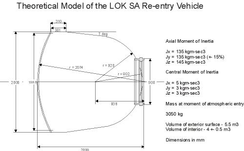
- SA (Spuskaeniy Apparat) - Descent module. In common with the L1 circumlunar version of Soyuz this version of the SA had a thicker heat shield, and seems to have had two hatches - the standard hatch at the apex, leading to the BO, and a side hatch allowing direct access to space. In the case of the L1, the presence of this lateral hatch meant the reserve parachute had been deleted. The two crew were seated in standard Soyuz seats to either side of a large central structure that housed additional life support equipment, the Krechet lunar surface suit, and lunar samples on the voyage home. The mass of the module is given as 2850 kg at launch, but another drawing shows a mass of 3050 kg at re-entry (perhaps including the lunar samples and the cosmonauts). Based on a control panel exhibited at MAKS 99, the LOK had controls somewhat different from those in the contemporary 7K-OK or L1 versions of the Soyuz. The sequencer panel had the 'on' and 'off' selector buttons to either side of the sequencer windows numbered, as on other versions, but the columns had functional headings, unlike the letters normally used. The SA was 2007 mm long and had a diameter of 2200 mm. Interestingly, a 'theoretical model' of the LOK SA at MAI shows a cylindrical section above the heat shield, as opposed to the conical section of the standard Soyuz. This is not seen on other models or drawings of the LOK.
- PO (Perekhodnoy Otsek) - Transition compartment. This was a truncated cone connecting the SA to the aft of the spacecraft. It was depressurized and housed four pairs of larger translation engines canted slightly forward so that they went through the spacecraft's center of gravity. They allowed up/down/right/left maneuvers in three dimensions during docking operations. Propellant was provided from the Block I propellant system.
- PO (Priborniy Otsek) - Equipment compartment. This was a pressurized cylinder with forward and aft hemi-ellipsoidal pressure bulkheads, similar to that used in other Soyuz models. It contained avionics - communications, telemetry, and command-link units. Most important of these was the digital computer of Pilyugin's guidance system by developed by NIIAP. This guided not only the LOK, but also the entire L3 stack throughout all flight phases from translunar injection from earth orbit through to return to earth. The guidance system was provided position and orientation data from a full-time inertial navigation unit, also by Pilyugin.
- AO (Agregatniy Otsek) - Engine compartment. On the LOK, this was a cylinder fitting and carrying loads over the outside of the spherical propellant tank of the Block I trans-earth injection propulsion system. It was covered on the outside with 24 extremely fragile hinged thermoregulation panels.
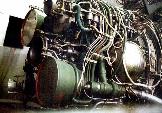
- Block I - This integrated propellant tank/engine assembly was developed by Isayev. It contained 3,152 kg of N2O4/UDMH propellants contained in a spherical 1.9 m diameter tank with a common bulkhead between the oxidizer and fuel. This tank fed two primary engine assemblies:
- The two-nozzle S5.51 engine had a total thrust of 3,388 kgf, a specific impulse of 314 seconds, and was used for the 1100 m/s trans-earth injection maneuver at the end of lunar orbit operations.
- The S5.51 was flanked by the two smaller nozzles of the S5.53 engine. With a total thrust of 417 kgf and a specific impulse of 296 seconds, this was used for lunar orbit maneuvers and mid-course corrections on the way back to earth. It was rated for 35 firings. The same engine was used in the lunar flyby spacecraft (Soyuz L1, L1E, L1P, and L1S) and was a close relative of the two-nozzle back-up engine used on the Soyuz 7K-OK orbiter.
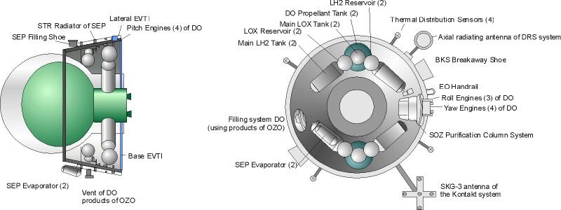
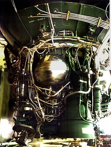
- EO (Energo-Otsek) - Power Module. This compartment was the flared base of the LOK. It connected the LOK to the payload shroud surrounding the LK and Block D stages during the trip to the moon until the LK/Block D separated from the LOK. The center of the space was taken up with the shrouded engine assembly of the Block I. Arranged within the periphery of the truncated cone were four fuel cells, their associated liquid oxygen and hydrogen tanks, and a refrigerator unit to keep the cryogenic liquids in liquid state. The outside of the EO was covered by tubular radiators of the refrigeration unit.
The use of a fuel cell was unique in the history of the Soviet space program and did not emerge again until the Buran shuttle orbiter of twenty years later. The Volna-20 fuel cells were developed by the Ural Electrochemical Enterprise. Each cells had a mass of 70 kg and could provide 1.5 kW of power at 27 V for 500 hours. The cells were fed by 600 kg of liquid hydrogen and oxygen. The water generated by the reaction of the hydrogen and oxygen was used by the crew.
Development and Flight History
Korolev had come up with using the lunar orbit rendezvous method for a lunar landing in response to the Soviet leadership demanding that he beat the Americans to the moon. Unfortunately, the leadership made this decision three years after the beginning of the Apollo project, and at the same time would not budget for more than four N1 launches a year. The only conceivable way of beating the Americans was to use a single N1 launch. But the N1 was designed to launch only 75 tonnes into low earth orbit, and OKB-1 calculations showed a minimum of 100 tonnes would be required for an LOR mission using Lox/Kerosene propellants in the booster.
Korolev was able to convince himself that by using a combination of modifications to the N1, chilled propellants, and modified trajectories he might be able to squeeze a 95 tonne payload out of the booster. This then had to be the total mass of the L3 assembly, including the trans-earth injection stage. This was the plan sold to the leadership, but as soon as development started it was apparent that a 95 tonne L3 would be unachievable.
The motivations for continuing were many. Mishin, Deputy Designer at OKB-1, wanted to go ahead with development of the N1 whether it could send a man to the moon or not. He believed it was critical to a range of future Soviet space projects and he was not about to kill it by telling the leadership it could not accomplish its only assigned mission. Bushuev noted the only way to get the necessary performance would be to use Lox/LH2 propellants in the second and third stages, as the Americans had done with the Saturn V. But this was not authorized in the approved draft project. Korolev was not about to tell the leadership that he had mis-estimated in their original proposal, or that Russian engines were not as good as American engines.
Two days after the N1-L3 one-shot scheme had been approved, a council of Chief Designers met to consider how to accomplish it. The use of Lox/LH2 stages was proposed to boost payload, but rejected due to the lack of Soviet experience with the propellants. The use of higher-performance N2O4/UDMH engines from Glushko was proposed, but again rejected by OKB-1. The designers became prisoners of their positions. There was no choice but to proceed with 95 tonne L3 as proposed. But this meant that the spacecraft estimated masses had no reserves. The LK mass was absurdly optimistic. During development the engineers would fight over grams of mass for subsystems.
The weight restrictions had consequences. By 20 December 1965 difficulties and arguments over development of the guidance system had reached a head. Pilyugin, the guidance subcontractor, wanted to use the latest technology in order to meet the weight and power consumption goals, including a digital computer and a gyroplatform of his own design. This was contrary to the decree, which required him to use a gyro platform from the customary supplier of OKB-1, Kuznetsov at NII-944. Pilyugin was reporting that he wouldn't have a guidance system ready for the N1 booster until late1968, let alone systems for the LOK and LK. Therefore an expert commission was convened by Keldysh, Head of the Soviet Academy of Sciences.
Korolev kicked off the meeting by complaining that if he had another 800 kg in payload mass, existing systems could be used. Pilyugin and Ryazanskiy provided an overview of their guidance systems, showing the concepts and the mass problems. The first launches could be made with the analogue systems desired by OKB-1, but the digital system would be required to conserve fuel cell consumables and accomplish a lunar landing mission. A discussion of fuel cell contractors led to a suggestion to use radio-isotope thermal generators (RTG's) from the KB Atomic Machinery Factory in the Urals. They had worked with Korolev for years on development of nuclear electric propulsion. But it was decided that there was no technical basis for proving reliable operation of RTG's in a vacuum. In addition, the fuel cells produced water for the crew, which would have to be carried separately if RTG's were used.
A month later Korolev was dead, and OKB-1 was without a Chief Designer. The leadership argued over the subject all during 1966. In the meantime, the American Apollo program was progressing rapidly, while the L3 project languished. It had become clear that a Soviet lunar landing could not be accomplished earlier than 1970, while the Americans were hoping for a landing in 1968 if all went well. By October 1966 the launch plan had slipped to the following:
- N1 2L, 3L, and 4L would take L1S unmanned spacecraft on lunar flybys with recovery of the capsule on earth in 1968-1969
- N1 5L and 6L would launch piloted LOK's with automated LK landings on the lunar surface in 1969-1970
- N1 8L, 9L, and 10L would carry manned Soviet lunar landing missions no earlier than 1970
It was also becoming apparent that the weight optimists were fighting a losing battle and that the N1 simply could not accomplish the one-launch scenario. This led to an examination of alternate launch plans. Meanwhile, amid a great deal of finger-pointing in the leadership, the decision was finally taken to appoint Mishin head of what was now dubbed TsKBEM in December 1966. The program lurched forward with the actual scenario for a lunar landing in constant flux.
Hardware development experienced continued delays. By the end of 1966 the Block I propulsion system was scheduled for its first ground tests in July 1967. New communications systems (Foton and Mezon) required to handle multiple manned spacecraft were not to be installed at ground stations until the end of the year.
Bushuev came up with plan in 1967 that provided for added safety through the use of two Proton and two N1 launches to get a single man safely to the lunar surface and back. Under this scenario, two Proton rockets would launch automated Ye-8LS lunar rovers to the surface. These would scout the local terrain. The rover would park at the selected site and serve as a beacon for the LK landers that would follow. An N1 would be launched with an unmanned LOK and the backup 'reserve' unmanned LK (LKr). The LKr would land with minimum propellant consumption, homing in on the Ye-8LS beacon. The LOK would photograph the site from lunar orbit and then return the film to earth. One month later, the manned expedition would be launched. A single cosmonaut would ride a second LK to the lunar surface, again using the homing beacon. If there were any problems, the cosmonaut could walk or drive one of the rovers to the LKr and have a second chance to get back to the LOK in lunar orbit. The Ye-8LS were equipped with a driver control panel and supplies of oxygen and water for the Krechet suit. They rover reach 1.2 km/hour for a slow-motion ride to the other lander if necessary.
Also in 1967 a substantive plan for test of the LOK in earth orbit was developed. The earth-orbit versions of the LOK was dubbed the T1K. By March 1968 it was planned three flights would be made launched by Chelomei's Proton booster in October-November 1968. The last of these would be manned and involve docking with the T2K test version of the LK lunar lander. In August 1968 discussion of using the Yastreb lightweight space suit for these missions was underway, Incredibly, at the same time, fundamental arguments over the rendezvous and docking system continued. Some factions preferred the Igla system which was being proven on the orbital version of Soyuz. Others preferred the Kontakt system. The decision, inexplicable in retrospect, was to continue with the Kontakt system for the L3.
Following the successful flight of Apollo 8 around the moon in December 1968 the project managers finally realized they had no chance for beating the Americans to a lunar landing. N1's 3L through 6L would not have enough payload for a landing mission. The LOK and LK were not nearly finished and the landing scenarios had been redrafted three times since the project had begun. A council of chief designers considered the options:
- Continue with the current hardware, using a two-launch N1 scenario. This was supported by Kryukov, Mozzhorin, Pilyugin, and Ryazanskiy.
- Develop an uprated N1 with a Lox/LH2 upper stage and new spacecraft. The favored configuration would by the N1F-V4. Two would be used to launch a completely new L5 complex, which would allow 4 to 5 cosmonauts to live for up to two months on the lunar surface. This had the potential to leapfrog the Americans rather than merely match their feat. This was pushed by OKB-1 engineers but would involve substantial additional funds.
A meeting of the Council of Chief Designers on 24 January 1969 made some brutal recommendations to the Soviet leadership. The T1K, T2K, and L1E were cancelled. The LOK and LK, although overweight, would continue in low-priority development. A month later the first launch attempt was made with the N1. N1 3L cleared the pad but an engine control system fault shut down all first stage engines after 68 seconds of flight. It was considered a typical first flight test and the program was not jeopardized.
On 29 and 30 May 1969 the launch commission for the next launch, N1 5L, was held. Mishin pushed for a decision, if 5L was successful, to launch the first LOK aboard N1 6L by the end of 1969. Mishin expected to have an all-up spacecraft by then, fully equipped with the fuel cells, the digital computer from NIIAP, the Kontakt docking system, and the Geofizika optical docking system. The cryogenic lox and LH2 for the LOK's fuel cells would be pumped aboard the spacecraft once the rocket was on the pad. The safety issues of handling LH2 was a source of continuing concern for the military. There was also a great deal of skepticism of Mishin's ability to produce a complete LOK by year's end.
Following the spectacular failure of N1 5L on 3 July 1969 the flight schedule was modified again. It now read as follows:
- In 1970 - launch of N1 6L and 7L with Soyuz 7K-L1S payloads
- In 1972 - launch of N1 8L, 9L, and 10L with LOK payloads on automated lunar orbit missions. The LOK's for these automated flights would be equipped with photographic equipment for surveying potential landing sites.
- In 1973 - launch of N1 11L, 12L, and 13L on piloted lunar orbit missions
- In 1974 - launch of N1 14L, 15L, and 16L to accomplish two lunar landings (evidently the first flight to provide the reserve LK for the next two flights).
Work continued on the LOK. Arsenal was still having problems in January 1970 with the forward engine system. By February 1970, of 16 LOK's authorized, only three were in ground test for possible future flight operations. Seven were partially assembled, and the remainder existed only as unassembled parts.
A crash program had been initiated to develop the Salyut 1 space station before the American Skylab. Development of the LOK and LK were given a very low priority. On 14 April 1971, at an expert commission reviewing the N1, Keldysh suddenly changed his long-standing support for the L3 and listed a series of 'mandatory changes' which would completely invalidate the LOK/LK design. Among these were:
- Use of redundant Kontakt or other systems for docking
- Inclusion of an internal transfer hatch, as had been developed for the Salyut station. This would eliminate the need for the lunar landing astronaut to spacewalk to the LK
- Re-integration of the use of Babakin's Ye-8LS surface robots into the mission plans to provide pre-landing site surveys, homing beacons, and backup surface transportation
- Elimination of the possibility of splashdown in the ocean in the event of guidance failure during capsule re-entry.
It was decided not to risk functional spacecraft in further N1 tests until the booster had proven itself. Therefore 6L and 7L would carry only LOK and LK mass models, with 8L now scheduled to carry an all-up automated LOK and LK spacecraft. During 1971, LOK certification tests began in earnest, including water-landing tests and launch escape system live fire tests. The fuel cells were finally tested in 1971-1972, producing 4.5 kW at 60% efficiency.
By this time, however, Mishin's team was already concentrating on a completely new spacecraft - the L3M - that would make a direct landing on the lunar surface. This would be joined to new Lox/LH2 propulsion stages in earth orbit using multiple N1F launches - the same scenario originally advocated by Korolev. A state commission under Keldysh studied the alternatives throughout 1971, and the final conclusion was to abandon any use of the original L3 (LOK+LK) lunar orbit rendezvous spacecraft in a manned landing. The assets already built would be used only for unmanned tests of the N1. Any Soviet manned lunar landing would rely on the L3M and multiple N1F launches to support a landing no earlier than 1977. But these plans were never fully funded, and in the absence of any formal go-ahead, Mishin continued to complete qualification and flight test of the LOK.
Therefore the payload for N1 7L was changed again, to be the first actual test flight of the LOK (article 6A was selected for the honor). A mock-up of the LK would accompany it on a lunar orbital mission. The flight plan for the mission was issued on July 19, 1972. N1 7L was to place the 89,803 kg L3 stack into a 200 x 740 km earth orbit at a 50.7 degree inclination. After 24 hours of on-orbit tests the Block G translunar injection stage would hurl the payload toward the moon. However even with the underweight payload the Block G could not complete its mission in this configuration. The Block D would have to fire for 44 seconds after the Block G had depleted its propellants in order to reach earth escape velocity. In case of a failure to reach a lunar trajectory, the LOK was to separate, conduct operations in earth orbit, and then deorbit for a splashdown in the Indian Ocean.
After four days transit to the moon, with two mid-course corrections, the Block D would fire to place the assembly into a 175 km circular lunar orbit at 98.5 hours into the flight. The Block D would shape the orbit to a final 40 km x 175 km orbit on maneuvers on the fifth and 27th orbits. The LOK was to conduct photographic sessions of potential future landing sites on orbit 14, 17, 34, and 36. After 3.7 days in lunar orbit, the LOK's forward living compartment would separate and the Block I engine would fire to put the spacecraft on a translunar trajectory. Eight minutes prior to re-entry the descent module would separate, curve around the north pole of the earth, and splash down in the Indian Ocean.
The digital computer and inertial platform aboard the LOK were responsible for guiding the Block G, Block D, and LOK during all flight maneuvers after earth orbit insertion. The computer used Tropa integrated microprocessors developed by the Ministry of Electronic Industry. During integration and test of the L3 assembly at Area 2B at Baikonur, many problems arose with the digital computers. Clearing them became a pacing item for the launch. Although electrical tests were completed on 14 October 1972, computer glitches on 27 October led to further delays. At the
More at: Soyuz 7K-LOK.
Family: Lunar Orbiters, Moon. Country: Russia. Engines: KTDU-53. Spacecraft: L3, DLB Lunar Base, LOK PAO, Soyuz 7K-LOK SA, Soyuz 7K-LOK BO. Launch Vehicles: N1, N1 1969. Propellants: N2O4/UDMH. Projects: Lunar L3. Launch Sites: Baikonur, Baikonur LC110L. Agency: Korolev bureau. Bibliography: 125, 164, 165, 168, 21, 283, 288, 367, 376, 474, 72, 75, 77, 89, 6898, 13123.
 | LOK Cutaway Detail Credit: © Mark Wade |
 | LOK EO Detailed cutaway of LOK Power Module. Credit: © Mark Wade |
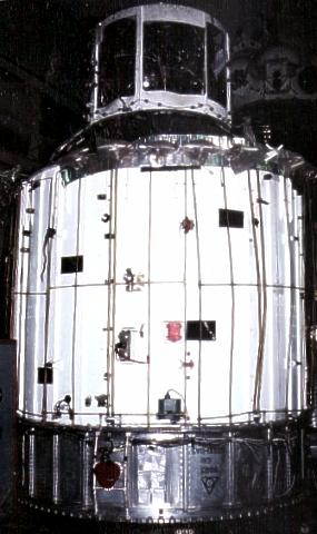
 | LOK DM Mass model of LOK descent module for reentry from lunar distances. Credit: © Mark Wade |
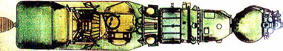
 | LOK Overhead Overhead view of LOK lunar orbiter. |
 | Kontakt Docking Mech Kontact docking grappler. The three arms at the bottom faced outward from the docking assembly. MAI, March 1994 Credit: © Dietrich Haeseler |
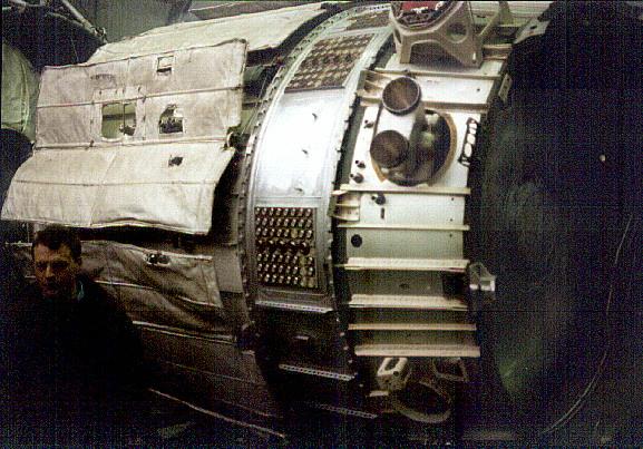
 | LOK Docking Assy Close-up view of LOK orientation engine unit and docking assembly at Korolev School. The docking system in this example is covered with flat plates. Credit: Jakob Terweij |
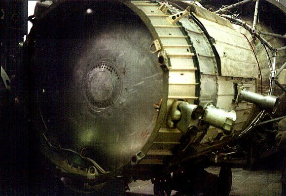
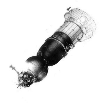
 | LOK reaction control The upper half of this item is the ODOP (Orientation and docking engine section) of the LOK, mounted at the top of the orbital module. The cone at top was had grapples for snagging the hexagonal grid of the large disk on top of the LK. Propellants for the orientation and manoeuvring engines were in the tanks in this section. The bottom half of this item is similar to a test installation used on the Soyuz 7K-L1S destroyed in the several N1 launches. Credit: © Mark Wade |
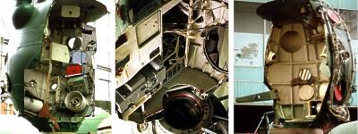 | LOK OM Three views of sectioned LOK orbital module at MAI. Credit: © Mark Wade |
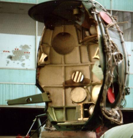 | LOK OM View View of LOK OM toward hatch. The cupola for docking is the circular depression in the to of the wall. Credit: © Mark Wade |
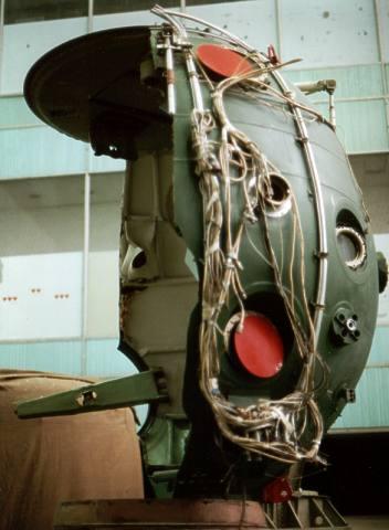 | LOK OM View View of LOK OM exterior, view toward hatch on far wall. The red covers and other exterior portholes are for the cameras of the lunar surface photography system. Credit: © Mark Wade |
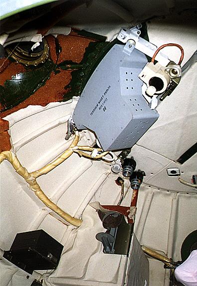
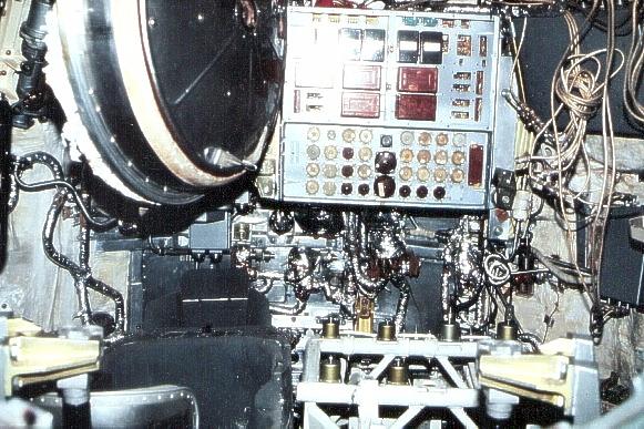
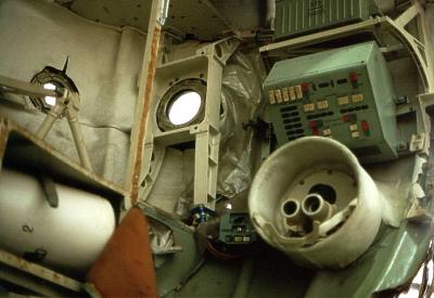 | LOK controls Work station inside LOK orbital module. These are the controls for the lunar photography system. Credit: © Mark Wade |
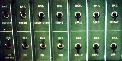 | LOK controls LOK OM circuit breaker panel toggle switches. The two on the top left are for the Krechet and Orlan suit circuits. Credit: © Mark Wade |
 | LOK Orbital Module LOK Orbital Module, view down from top of spacecraft toward Soyuz descent module. The main control panels of the OM fill the wall to the left. The area also holds the cabin pressurisation system and storage for the Krechet moon suit. Credit: © Mark Wade |
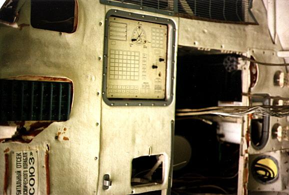 | LOK Orbital Module LOK Orbital Module, view of main control panel dummy. The standard chronograph and sequencer switches were here. Credit: © Mark Wade |
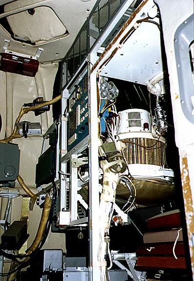 | LOK Orbital Module LOK Orbital Module, view up from the entry hatch from the Descent Module to the ceiling. Note air conditioning equipment. Credit: © Mark Wade |
 | LOK Orbital Module LOK Orbital Module, equipment above the EVA hatch. These mock-ups are at the location of the spacesuit hook-ups for the single cosmonauts spacewalks to and from the LK. Credit: © Mark Wade |
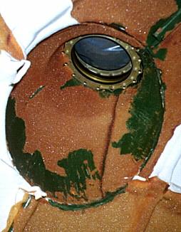 | LOK Orbital Module LOK Orbital Module, close-up of cupola for use of cosmonaut in docking with LK. Credit: © Mark Wade |
 | LOK Orbital Module LOK Orbital Module, docking control station. The manoeuvring panel and controls were located where the grey dummy panel is. It is flanked by hand controllers. The cosmonaut would look through the cupola to accomplish manual docking with the LK after its return from the lunar surface. Credit: © Mark Wade |
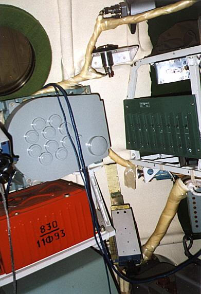
 | LOK Orbital Module LOK Orbital Module control station above hatch entrance. Main controls are on the blue panel; the green panel is a breaker panel. Credit: © Mark Wade |
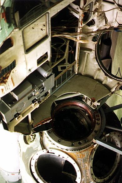
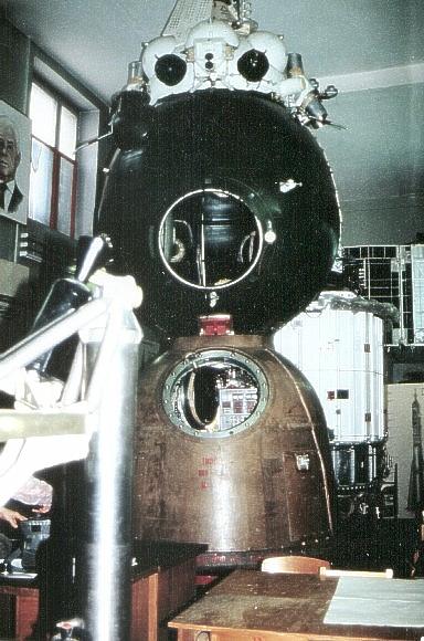
 | LOK Descent Module LOK Descent Module and Orbital Module. Note the cupola at the left top of the Orbital Module. On the opposite wall are the lunar mapping camera apertures and control station. Credit: © Mark Wade |
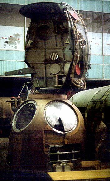 | LOK Descent Module LOK Descent Module and Orbital Module Credit: © Mark Wade |
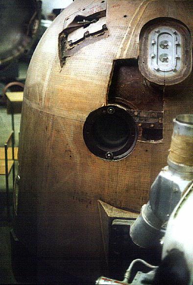 | LOK Descent Module LOK Descent Module detail. The ablative material is far thicker than on the standard Soyuz descent module for the re-entry from lunar distances at twice the energy as that from earth orbit. Credit: © Mark Wade |
 | LOK at Korolev LOK exhibited at Korolev School. Living module and re-entry vehicle are at foreground; in background is Block I instrument/propulsion unit covered with heat radiating panels. Credit: Jakob Terweij |
 | LOK SA Interior View of the interior of the LOK re-entry vehicle at the Korolev School. This is the only known photograph of this part of the spacecraft. A form-fitting crew couch is seen at lower left and a single visible control panel is at centre. Credit: Jakob Terweij |
 | DM Thrusters Detail of thrusters of Soyuz / L1 descent module. These hydrogen peroxide monopropellant thrusters provided orientation of the capsule before and during re-entry. Credit: © Mark Wade |
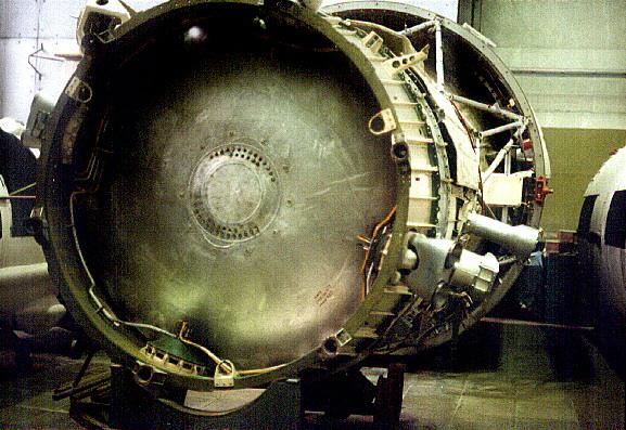 | LOK Block I forward View of the dome covering the pressurized instrument compartment of the LOK. Credit: © Mark Wade |
 | LOK Block I side View of the LOK Block I. Noticeable are the fragile radiator panels, and the large manoeuvring thrusters at the forward end. The large cylindrical devices are sensors of the attitude control system. Credit: © Mark Wade |
 | LOK Navigation Coordinate system and sensors of the LOK astronavigation system. The 106K sensors detected the centre of the solar disk; the 107K sensor the centre of the earth or moon; and the 100K sensors fixed stars. MAI, March 1994 Credit: © Dietrich Haeseler |
 | LOK Block I side View of the LOK Block I instrument/rocket module. The fragile radiators, arrayed around the main fuel tank, extended away from the body of the spacecraft in flight. The silvery instrument section has numerous patch panels for connecting external wiring. The tapered interstage with stringers connected to the Soyuz descent module. Large 'mooring' thrusters arrayed around this section provided high-authority manoeuvring capability for the LOK in its rendezvous and docking with the LK. Credit: © Mark Wade |
 | LOK Block I The LOK Block I propulsion unit at Korolev. The delicate white radiator panels have been bent over the years. The cylinder outer shell and flared base of the LOK are missing; the smaller cylinder at top is the engine unit. Credit: Jakob Terweij |
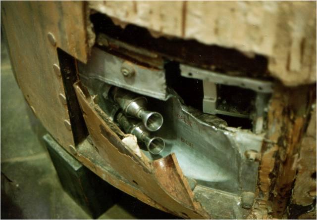
 | S5.51 LOK engine Side view of the twin-chamber Isayev S5.51 engine used in the Soyuz 7K-LOK lunar orbiter. The two smaller chambers of the S5.52 supplemental engine protude beyond the main engine bells to either side. Credit: © Mark Wade |
 | S5.51 LOK engine The complex plumbing fed numerous smaller attitude control thrusters at the base of the LOK. Credit: © Mark Wade |
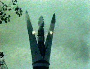 | N1-L3 shroud Rare shot of n N1-L3 shroud separation test. Proof that the hardware development reached an advanced phase. Credit: RKK Energia |
 | LOK-LK Drawing Unusual alternate diagram of LOK and LK lunar craft in docked configuration, with bottom view of LK. Korolev School. Credit: Jakob Terweij |
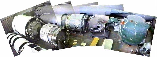 | Panorama MAI Exhibit Panorama of launch vehicles and spacecraft exhibited at Moscow Aviation Institute. The BO and SA of the LOK are at the right; the Block I is at middle left, in front of an L1 Block D. Credit: Ed Cameron |
 | Korolev and Isayev Credit: © Mark Wade |
 | GE Apollo vs Soyuz Comparison of GE Apollo and Soyuz LOK lunar orbiter spacecraft. |
 | LOK Lunar Orbiter The Soyuz 7K-LOK lunar orbiter spacecraft to be used in the L3 lunar landing project complex. Credit: © Mark Wade |
 | Zond Credit: Manufacturer Image |
 | N1-L3 drawing N1-L3 drawing at Kaluga Credit: © Mark Wade |
 | L3 Cutaway Dimensioned Russian cutaway drawing of L3 manned lunar landing complex. |
1964 July 19 - .
- Korolev obtains preliminary approval for a single-launch, lunar orbit rendezvous, manned landing. - .
Nation: Russia.
Related Persons: Bushuyev,
Chelomei,
Feoktistov,
Glushko,
Korolev,
Mishin,
Smirnov,
Yangel.
Program: Lunar L3,
Lunar L1.
Spacecraft: L3-1963,
LK,
LK-1,
Soyuz 7K-LOK.
Work on the original N1-L3 had begun in 1963. This had been preceded by two years of working on a draft project for the LK lunar lander and its propulsion system. But there was no money for full scale development -- no code name from Gosplan against which to charge such work. It was annoying that Chelomei, Glushko, and Yangel were wasting resources on alternate designs at the same time. Additional Details: here....
1964 July 21 - . Launch Vehicle: N1.
- Korolev's single-launch lunar scheme reviewed by the Chief Designers - . Nation: Russia. Related Persons: Glushko, Isayev, Keldysh, Khrushchev, Korolev, Kuznetsov, Pilyugin, Smirnov. Program: Lunar L3. Spacecraft: LK, Soyuz 7K-LOK. How to achieve the additional N1 payload was a key point of discussion.. Additional Details: here....
1964 July 27 - .
- Space simulator plans - .
Nation: Russia.
Spacecraft: LK,
LK-1,
Soyuz 7K-LOK,
Soyuz A,
TMK-1,
TMK-E.
A two-day conference is held at IAKM to review requirements for trainers and task simulators over the next 6 to 7 years. The plan includes basic instructional versions of planned spacecraft, trainers for flying around the moon, and a mock-up of the TMK Heavy Interplanetary Spacecraft. These will require a new facility of to 7,000 square metres. Trainers and strands at TsPK will be housed in building D, a hangar-type facility. The TBK-60 thermal/barometric chamber will be housed in a single hangar. To fully specify TsPK trainers and stands for the lunar mission, trainers for space navigation, and military combat spacecraft will not be completed until 1965.
1964 August 1 - .
- Full scale development of Soviet manned lunar flyby and landing projects authorised. - .
Nation: Russia.
Related Persons: Chelomei,
Korolev.
Program: Lunar L1,
Lunar L3.
Flight: Soyuz A-1,
Soyuz A-2,
Soyuz A-3,
Soyuz A-4.
Spacecraft: LK,
LK-1,
Luna Ye-8,
Soyuz 7K-LOK,
Soyuz A.
Central Committee of the Communist Party and Council of Soviet Ministers Decree 655-268 'On Work on the Exploration of the Moon and Mastery of Space--piloted LK-1 circumlunar and L3 lunar landing projects and the Ye-6M lunar lander' was issued. Chelomei was to develop the three-stage UR-500K booster and LK-1 spacecraft for the manned lunar flyby. Korolev was to develop the totally different N1 booster and L3 spacecraft complex for the manned lunar landing. First launch of the N1 was to be by the first quarter 1966, with manned lunar landings in 1967 to 1968. Reprioritization led to work being stopped on Korolev's Zvezda 6-man orbiting weapons platform by mid-1965, after a huge mockup had been built.
Korolev felt that if he had the full support of the Communist Party, the military, and industry he could achieve this goal, and this decree ordered such support. The USSR would be first on the moon. But in truth the draft project behind the decree had not solved all of the technical problems, or provided a solution on how to achieve the required payload on either the booster or spacecraft side. New technology features required for success of the scheme included an advanced guidance system in the N1 third stage equipment bay, the enormous fuel tanks in the N1 first stage, and the Lox/LH2 fuel cells needed for the LOK lunar orbiter. But the real technical problem with the N1-L3 design was the total lack of any weight growth reserve. Even thought the systems had not even been developed yet, engineers were fighting over tens of grams in their weight allocations, let alone the kilograms normally at issue.
Development of Korolev's Soyuz A-B-V, a competing circumlunar project, was evidently still authorised, although it duplicated Chelomei's LK-1.
1964 October 28 - .
- Lunar project orders issued to industry. - . Nation: Russia. Program: Lunar L1, Lunar L3. Spacecraft: LK, LK-1, Luna Ye-8, Soyuz 7K-LOK. Military-Industrial Commission (VPK) Decree 'On assignment of lunar programs to OKB-52 and OKB-1' was issued..
November 1964 - .
- Korolev's admits that N1 cannot attain payload needed for single-launch mission - .
Nation: Russia.
Related Persons: Babakin,
Brezhnev,
Chelomei,
Khrushchev,
Korolev,
Kozlov,
Lavochkin,
Ustinov,
Yangel.
Program: Lunar L3.
Spacecraft: LK,
LK-700,
Soyuz 7K-LOK.
Korolev speaks privately to Chertok. Kozlov has told him it will be impossible to build an N1 with the 93 tonne payload capability until the fourth flight article. The L3 concept was still the same as in the August decree - 2 cosmonauts aboard the LOK orbiter, one aboard the LK lander. Korolev asks Chertok to take 800 kg out of the weight budget for the L3. Chertok informs him that they are already 500 kg over the August budget. This is still without all the unknowns of the automated lunar landing being solved. Additional Details: here....
During 1965 - . Launch Vehicle: N1.
- N1 development issues - .
Nation: Russia.
Related Persons: Korolev,
Pilyugin,
Raushenbakh.
Program: Lunar L3.
Spacecraft: LK,
Luna E-6,
Soyuz 7K-LOK.
There were two camps on the N1-L3 control systems. One group was within OKB-1, and had developed the systems for the Vostok and Zenit spacecraft, under the personal oversight of Korolev. They stressed the maximum quality and reliability in their systems. The second group had worked with Pilyugin, and had designed the systems for the Mars, Venus, Luna E-6 probes, the R-9, RT-1, RT-2, and GR-1 missiles; and piloted spacecraft. Their design emphasis was on maximum usability and output. Pilyugin had been named chief designer of the control system for the N1-L3. Additional Details: here....
1965 February 10 - . Launch Vehicle: N1.
- L3 single-launch spacecraft draft project approved. - .
Nation: Russia.
Related Persons: Keldysh,
Korolev,
Pilyugin.
Program: Lunar L3.
Spacecraft: LK,
Soyuz 7K-LOK.
Interdepartmental Scientific-Technical Council on Space Research (MNTS-KI) Decree 'On approval of the L3 draft project' was issued. The decree followed a review by a Keldysh-led Academy of Sciences state commission the previous December. The decree moved the first flight of the N1 to the end of 1966. Additional Details: here....
Spring 1965 - . Launch Vehicle: N1.
- Guidance system for N1 cannot support planned schedule - . Nation: Russia. Related Persons: Korolev, Pilyugin. Program: Lunar L3. Spacecraft: LK, Soyuz 7K-LOK. By the second quarter of 1965 Pilyugin was already notifying OKB-1 that he could never have the booster guidance system ready for the planned first launch in 1968 - not to even mention the systems for the LOK and LK..
1965 July 6 - .
- Soyuz hot mock-up - .
Nation: Russia.
Related Persons: Korolev.
Program: Soyuz.
Spacecraft Bus: Soyuz.
Spacecraft: Soyuz 7K-LOK.
Chertok argues for the necessity of adding one Soyuz to production and using it as an iron bird - a hot mock-up on which avionics and electrical systems can be integrated and tested. Gherman Semenov and Turkov convince Korolev that this cannot be done within the existing schedules.
1965 September 1 - . LV Family: N1. Launch Vehicle: N1 1964.
- Voskhod/Soyuz crewing plans - .
Nation: Russia.
Related Persons: Anokhin,
Artyukhin,
Bykovsky,
Gagarin,
Katys,
Kolodin,
Komarov,
Korolev,
Matinchenko,
Nikolayev,
Ponomaryova,
Solovyova,
Volynov.
Program: Voskhod,
Soyuz,
Lunar L3.
Flight: Soyuz 1,
Soyuz 2A,
Soyuz s/n 3/4,
Voskhod 3,
Voskhod 5.
Spacecraft: LK,
LK-1,
Soyuz 7K-L1,
Soyuz 7K-LOK,
Voskhod.
Kamanin meets with Korolev at 15:00 to discuss crew plans. As Soyuz pilot candidates, Kamanin proposes Gagarin, Nikolayev, Bykovsky, Komarov, Kolodin, Artyukhin, and Matinchenko. Korolev counters by proposing supplemental training of a supplemental group of engineer-cosmonauts from the ranks of OKB-1. He calls Anokhin, his lead test pilot, informs Korolev that there are 100 engineers working at the bureau that are potential cosmonauts candidates, of which perhaps 25 would complete the selection process. Kamanin agrees to assist OKB-1 in flight training of these engineer-cosmonauts. Kamanin again proposes Volynov and Katys as prime crew for the Voskhod 3 12-15 day flight. Korolev reveals that, even though Kamanin will have the crew ready by October, the spacecraft for the flight may not yet even be ready by November - Kamanin thinks January 1966 is more realistic. The discussion turns to the female EVA flight - Ponomaryova as pilot, Solovyova as spacewalker. It is decided that a group of 6 to 8 cosmonauts will begin dedicated training in September for lunar flyby and landing missions. Korolev advises Kamanin that metal fabrication of the N1 superbooster first article will be completed by the end of 1965. The booster will have a payload to low earth orbit of 90 tonnes, and later versions with uprated engines will reach 130 tonnes payload. Korolev foresees the payload for the first N1 tests being a handful of Soyuz spacecraft.
1965 September 6 - . Launch Vehicle: N1.
- Problems in lunar projects addressed. - . Nation: Russia. Spacecraft: LK, Soyuz 7K-L1, Soyuz 7K-LOK. Ministry of General Machine Building (MOM) Decree 'On delays in work on piloted lunar programs' was issued..
1965 December 20 - . Launch Vehicle: N1.
- Decision to use analogue guidance in early N1 launches - . Nation: Russia. Related Persons: Keldysh, Korolev, Pilyugin, Ryazanskiy. Program: Lunar L3. Spacecraft: LK, Soyuz 7K-LOK. Pilyugin called Keldysh to tell him he had heard that Keldysh again wanted to form an expert commission to study guidance system development problems with the N1, with Bushuyev as the head.. Additional Details: here....
1965 December 31 - . LV Family: N1. Launch Vehicle: N1 1964.
- Daunting year ahead - .
Nation: Russia.
Program: Voskhod,
Soyuz,
Lunar L1.
Flight: Soviet Lunar Landing,
Soyuz 1,
Soyuz 2A,
Soyuz 7K-L1 mission 1.
Spacecraft: LK,
Soyuz 7K-L1,
Soyuz 7K-LOK,
Soyuz 7K-OK.
Kamanin looks ahead to the very difficult tasks scheduled for 1966. There are to be 5 to 6 Soyuz flights, the first tests of the N1 heavy booster, the first docking in space. Preparations will have to intensify for the first manned flyby of the moon in 1967, following by the planned first Soviet moon landing in 1967-1969. Kamanin does not see how it can all be done on schedule, especially without a reorganization of the management of the Soviet space program.
1966 January 24 - .
- New space schedules - .
Nation: Russia.
Related Persons: Afanasyev, Sergei,
Chelomei,
Korolev,
Malinovskiy,
Petrovskiy.
Program: Voskhod,
Soyuz,
Lunar L1.
Flight: Soviet Lunar Landing,
Soyuz 1,
Soyuz 2A,
Soyuz 7K-L1 mission 1.
Spacecraft: LK,
Soyuz 7K-L1,
Soyuz 7K-LOK,
Soyuz 7K-OK.
The VVS General Staff reviews a range of documents, authored by Korolev before his death, and supported by ministers Afanasyev and Petrovskiy. The schedules for the projects for flying around and landing on the moon are to be delayed from 1966-1967 to 1968-1969. A range of other space programs will similarly be delayed by 18 to 24 months. An institute for tests of space technology will be established at Chelomei's facility at Reutov. The IMBP will be made the lead organization for space medicine. Responsibility for space technology development will be moved from MOM to 10 other ministries. 100 million roubles have been allocated for the establishment of new research institutes. Kamanin is appalled, but Malinovskiy favours getting rid of the responsibility for these projects. The arguments over these changes - which reduce the VVS role in spaceflight - will be the subject of much of Kamanin's diary over the following weeks.
1966 February 17 - .
- Soviet Lunar Landing Plans - .
Nation: Russia.
Program: Lunar L3.
Flight: Soviet Lunar Landing.
Spacecraft: LK,
Soyuz 7K-LOK.
Kamanin presents his plan to train 5 to 6 crews for the lunar landing mission over a 30 month period. Only experienced cosmonauts, with prior spaceflight experience, will be assigned to these crews. Kamanin lays out for the VVS leadership the complex series of events the cosmonauts will have to complete in the L3 lunar-orbit rendezvous scheme, including transfer between spacecraft of a single lunar landing cosmonaut in free space in lunar orbit. Crews need to be formed immediately, with two cosmonauts per crew - the L3 mission commander, and the second cosmonaut who will land on the moon. In order to accomplish the mission on schedule, a new air regiment needs to be formed, with the necessary flying laboratories, simulators and trainers, space suits, test stands and surface simulators, and other equipment necessary to train the crew for the mission.
1966 March 6 - .
- Soviet design bureaux reorganised and renamed. - .
Nation: Russia.
Related Persons: Afanasyev, Sergei,
Mishin,
Okhapkin.
Spacecraft: LK,
Soyuz 7K-L1,
Soyuz 7K-LOK,
Soyuz 7K-OK.
Decree 'On renaming OKB-1 as TsKBEM and OKB-52 as TsKBM' was issued. In 1966 Afanasyev reorganised the military industrial complex. OKB-1 was redesignated TsKBEM. Sergei Osipovich Opakhin was made First Deputy within the new organization.
However within TsKBEM there were no relative priorities for the projects competing for resources. The R-9 and RT-2 ICBM's, the orbital, circumlunar, and lunar orbiter versions of Soyuz, the LK lunar lander, the N1 booster -- all were 'equal'. It seemed folly to be pursuing the orbital ferry version of the Soyuz when no space station had to be funded. But it was felt flying the spacecraft would solve reliability questions about the design, so it was pursued in parallel with the L1 and L3 versions.
1966 March 23 - .
- Inconsistent Soviet lunar program - .
Related Persons: Mishin,
Chertok.
Spacecraft: Block D,
Soyuz,
Soyuz 7K-L1,
Soyuz 7K-LOK,
Soyuz 7K-OK,
Soyuz Kontakt.
Acting director Mishin held a brainstorming session with this top managers to address "...our inconsistent lunar program". He noted then-current contradictory approaches: 1. Return to a two-launch scheme (podsadka, as baseline); 2. Keep with direct landing; 3. Use a Block D with storable propellants; 4. Use the 7K-OK as the designated return spacecraft. He noted that the L1 program was a diversion for the bureau to the core objective of landing a cosmonaut on the moon (the L3 program). Among the advantages of continuing with the L1, he noted that it "Utilizes the 7K-OK" - evidently there was no purpose for the spacecraft beyond the L1 mission in the podsadka scenario. He asks for frank opinions from his managers. V Rauschenbach noted that they "..have to do the L-1 … and therefore we will have to use a 2-launch scheme based on the L1-S". BE Chertok: discussed the rendezvous and docking systems for the various spacecraft: L1-S - "Igla"; LOK - "Kontakt" (since "Igla" cannot be used on the LOK (due to mass considerations); or a new system for the LOK. (Mishin Diaries 1-226) Here we have an indication that the L1 podsadka version did use the Igla system, which makes complete sense, since the Soyuz 7K-OK missions conducted dress rehearsals for podsadka using this system to rendezvous and dock two 7K-OK spacecraft in earth orbit.
1966 May 11 - . Launch Vehicle: N1.
- Mishin selected as Korolev's replacement after four-month delay - .
Nation: Russia.
Related Persons: Babakin,
Keldysh,
Khrushchev,
Korolev,
Mishin,
Mozzhorin,
Okhapkin,
Ustinov.
Program: Lunar L3,
Lunar L1.
Flight: Soyuz 1,
Soyuz 2A.
Spacecraft: LK,
Soyuz 7K-LOK.
From 1963-1965 Ustinov was both head of the Soviet for the National Economy and the First Secretary of the Presidium of Soviet Ministers. He supported civilian space projects and instructed the military to co-operate in them. But after Khrushchev was ousted, Ustinov had less influence with the Ministry of Defence.
After the death of Korolev in January, a letter was sent to the Central Committee requesting that Mishin be appointed director of OKB-1. Ustinov tried to line up support for Mishin, but by the time of the first first Saturn IB orbital flight on 26 February 1966, no decision had been made. America was progressing on the path to the moon, but Russia was stalled. An alternate that had been considered was Sergei Okhapkin, another Deputy Chief Designer at TsKBEM. But Okhapkin knew only spacecraft, he had never developed complete launch-booster-spacecraft systems. By the time Mishin was appointed, it was clear that the race was lost. The American's planned their first Saturn V launch in September 1967 and their first manned flight in 1968. Mishin could not expect trials of the LK lunar lander until 1969 at the earliest. There were insufficient funds allocated, and the schedule had no allowance for test flight failures. Ustinov, Morozhin, and Keldysh pointed fingers as to who had presented such unrealistic schedules to the Politburo. Keldysh now supported unmanned robot lunar landers in development by Babakin. Even these would not land until 1970, allowing three years of flight trials to achieve reliability. Khrushchev, it seemed, was to blame for such enormous unaffordable projects. This in turn put Ustinov in danger, as Khrushchev's point man for space.
1966 May 31 - .
- Commonality of theme for the L1 and L1S. - . Related Persons: Mishin, Litvinov, . Spacecraft: Soyuz, Soyuz 7K-L1, Soyuz 7K-L1S, Soyuz 7K-LOK. Mishin makes a note for himself (Mishin Diaries 1-284-285): "Get photos for VYa Litvinov of Blok D, 7K-L-1, 7K-L1S", indicating a commonality of theme for the L1 and L1S..
1966 September 1 - . Launch Vehicle: N1.
- N1-L3 manned landing profile approved. - . Nation: Russia. Spacecraft: LK, Soyuz 7K-LOK. Central Committee of the Communist Party and Council of Soviet Ministers Decree 'On approval of the N1-L3 mission profile' was issued..
September 1966 - .
- N1 two-launch moon scenario proposed - .
Nation: Russia.
Related Persons: Bushuyev,
Korolev.
Program: Lunar L3,
Lunar L1,
Soyuz.
Spacecraft: LK,
Molniya-1,
Soyuz 7K-L1,
Soyuz 7K-LOK,
Soyuz 7K-OK.
Bushuyev proposed a two launch variation on Korolev's single-launch scheme. The increased-payload version of the N1 with six additional engines was not planned to fly until vehicle 3L. 1L and 2L were to be technology articles for ground test with only the original 24 engine configuration. At that time the first Apollo test flight was planned by the end of 1966, and the US moon landing no later than 1969. The Soviets expected the first test of their LK lander in 1969, and concluded they could not expect to land a Soviet man on the moon until 1972. Additional Details: here....
1966 September 2 - .
- Cosmonaut civilian program training groups - .
Nation: Russia.
Related Persons: Bykovsky,
Dobrovolsky,
Gagarin,
Gorbatko,
Khrunov,
Kolodin,
Komarov,
Leonov,
Nikolayev,
Shatalov,
Volynov,
Voronov,
Zholobov.
Program: Soyuz,
Lunar L1,
Lunar L3.
Flight: Soviet Lunar Landing,
Soyuz 1,
Soyuz 2A,
Soyuz 7K-L1 mission 1,
Soyuz 7K-L1 mission 2,
Soyuz 7K-L1 mission 3,
Soyuz s/n 3/4,
Soyuz s/n 5/6,
Voskhod 3.
Spacecraft: LK,
Soyuz 7K-L1,
Soyuz 7K-LOK,
Soyuz 7K-OK.
Kamanin organises the cosmonauts into the following training groups:
- Soyuz 7K-OK: Gagarin, Komarov, Nikolayev, Bykovsky, Khrunov, Gorbatko, Voronov, Kolodin
- L1: Volynov, Dobrovolskiy, Voronov, Kolodin, Zholobov, Komarov, Bykovskiy
- L3: Leonov, Gorbatko, Khrunov, Gagarin, Nikolayev, Shatalov
Rudenko agrees with Kamanin's plan, except he urges him to assign more cosmonauts to the Soyuz 7K-OK group, and include OKB-1 cosmonauts in the 7K-OK, L1, and L3 groups, and Academy of Science cosmonauts in the L1 and L3 groups.
These cosmonaut assignments were in constant flux, and many cosmonauts were assigned to train for more than one program - resulting in multiple claims in later years that 'I was being trained for the first moon flight'.
1966 September 14 - . Launch Vehicle: N1.
- N1 plans approved. - . Nation: Russia. Spacecraft: LK, Soyuz 7K-LOK. Academy of Sciences Decree 'On course of work on the N1-L3' was issued..
1966 September 17 - .
- Competing lunar landing designs to be evaluated. - . Nation: Russia. Spacecraft: LK, LK-700, Soyuz 7K-LOK. Military-Industrial Commission (VPK) Decree 'On creation of a commission to compare the UR-700-LK-700 and the N1-L3' was issued..
1966 November 1 - .
- Delays in Soviet manned lunar programs addressed. - . Nation: Russia. Spacecraft: LK, Soyuz 7K-L1, Soyuz 7K-LOK. Decree 'On lag of work on the N1-L3 and UR-500K-L1 programs' was issued..
1966 November 10 - . Launch Vehicle: N1.
- Lunar coordination problems - . Nation: Russia. Program: Lunar L3. Class: Manned. Type: Manned spacecraft. Spacecraft Bus: Soyuz. Spacecraft: Soyuz 7K-LOK. Kamanin diary complains of lunar coordination problems..
1966 November 16 - .
- Government go-ahead for N-1 use in lunar program - .
Nation: Russia.
Related Persons: Chelomei,
Keldysh,
Mishin.
Program: Lunar L3.
Class: Manned.
Type: Manned spacecraft. Spacecraft: LK-700,
Soyuz 7K-LOK.
Mishin's draft plan for the Soviet lunar landing was approved by an expert commission headed by Keldysh. The first N-1 launch was set for March 1968. At same meeting, Chelomei made a last ditch attempt to get his revised UR-700/LK-700 direct landing approach approved in its place. Although Chelomei had lined up the support of Glushko, and Mishin was in a weak position after Korolev's death, Keldysh managed to ensure that the N1-L3 continued. However continued design work on the LK-700, the UR-700 booster, and development of the RD-270 engine were authorised.
1966 November 21 - .
- Soyuz crews agreed officially - .
Nation: Russia.
Related Persons: Anokhin,
Bykovsky,
Feoktistov,
Gagarin,
Gorbatko,
Kamanin,
Kerimov,
Khrunov,
Komarov,
Kubasov,
Mishin,
Nikolayev,
Rudenko,
Yeliseyev.
Program: Soyuz.
Flight: Soyuz 1,
Soyuz 2A.
Spacecraft: Soyuz 7K-L1,
Soyuz 7K-LOK,
Soyuz 7K-OK.
The weather continues to deteriorate, and Kamanin considers moving the Tu-104 and cosmonauts to Krasnovodsk in order to get the 24 necessary zero-G flights before launch. At 11:00 the State Commission meets at Area 31. Present are Kerimov, Mishin, Rudenko, Kamanin, Komarov, Bykovsky, Khrunov, Yeliseyev, Anokhin and others. Mishin describes the status of preparations of Soyuz s/n 1, 2, 3, 4 for launch. He notes that the L1 and L3 lunar spacecraft are derived from the 7K-OK, and that these flights will prove the spacecraft technology as well as the rendezvous and docking techniques necessary for subsequent manned lunar missions. Feoktistov and the OKB-1 engineers say a launch cannot occur before 15 January, but Mishin insists on 25 December. That will leave only 20 days for cosmonaut training for the mission, including the spacewalk to 10 m away from the docked spacecraft. Faced with the necessity for the crews to train together as a team prior to flight, Mishin at long last officially agrees to the crew composition for the flights: Komarov, Bykovsky, Khrunov, and Yeliseyev as prime crews, with Gagarin, Nikolayev, Gorbatko, and Kubasov as back-ups. However a new obstacle appears. KGB Colonel Dushin reports that Yeliseyev goes by his mother's surname. His father, Stanislav Adamovich Kureytis , was a Lithuanian sentenced to five years in 1935 for anti-Soviet agitation. He currently works in Moscow as Chief of the laboratory of the Central Scientific Research Institute of the Shoe Industry. Furthermore Yeliseyev had a daughter in 1960, but subsequently annulled the marriage in 1966.
Later Feoktistov works with the crews on spacecraft s/n 1 to determine the feasibility of the 10-m EVA. The cosmonauts suggest a telescoping pole rather than a line be used to enable the cosmonaut to be in position to film the joined spacecraft. Bushuyev is tasked with developing the new hardware.
1966 December 2 - . LV Family: N1, Proton, .
- The 2-launch N1 scenario was discussed in an interdepartmental technical review with MV Keldysh. - .
Related Persons: Mishin,
Bushuyev,
Keldysh,
.
Spacecraft: Block D,
Soyuz 7K-LOK,
LK,
Luna Ye-8.
At this point the Ye-8 would be delivered to the moon by a UR-500K launch vehicle. The basic constraint was the 5300 kg payload capability of the Block D to translunar injection. This meant tradeoffs in the accuracy of the Ye-8's initial landing versus its lifetime on the surface waiting for arrival of the LK. It was agreed that a working group would meet the next day to develop final specifications Ye-8 and a more detailed outline of the N1-L3 expedition using Ye-8. (start-up sequence, the time, the connections between LK, LOK and Ye-8, the means for determining the location). KD Bushuyev was to study the backup LK concept. (Mishin Diaries 1-235)
1966 December 31 - . Launch Vehicle: N1.
- 18 cosmonauts in lunar training - . Nation: Russia. Related Persons: Artyukhin, Belousov, Bykovsky, Dobrovolsky, Gagarin, Gorbatko, Gubarev, Gulyayev, Khrunov, Kolesnikov, Kolodin, Komarov, Nikolayev, Popovich, Volynov, Voronov, Zholobov. Program: Lunar L1. Class: Manned. Type: Manned spacecraft. Spacecraft Bus: Soyuz. Spacecraft: Soyuz 7K-LOK. Gagarin, Komarov, Nikolayev, Bykovsky, Khrunov, Gorbatko, Voronov, Kolodin, Popovich, Gubarev, Artyukhin, Gylyayev, Belousov, Kolesnikov, Volynov, Doborvolsky, Zhobolov..
1967 February 1 - . Launch Vehicle: N1.
- Government approves landing on moon by end 1968 - .
Nation: Russia.
Program: Lunar L3.
Class: Manned.
Type: Manned spacecraft. Spacecraft Bus: Soyuz.
Spacecraft: Soyuz 7K-LOK.
Soviet government approves plan to land cosmonaut on moon by end 1968. N-1 test plan approved, envisioning third quarter 1967 as beginning of flight hardware construction. Fall-back project would be manned circumlunar mission. First manned L1 mission imagined as early as June 1967. First N1 launch by March 1968.
1967 February 4 - . Launch Vehicle: N1.
- L1/L3 launch schedules set - .
Nation: Russia.
Program: Lunar L1,
Lunar L3.
Spacecraft: Soyuz 7K-L1,
Soyuz 7K-LOK.
The following is the schedule set be decree for the L1 and L3 projects:
Serial # Mission               Date
2P       Develop Block D stage Feb or Mar 67
3P       same                  Mar 67
4L       Unmanned lunar flyby  May 67
5L       Unmanned lunar flyby  Jun 67
6L       Manned lunar flyby    Jun or Jul 67
7L&8L    Manned lunar flybys   Aug 67
9L&10L   Manned lunar flybys   Sep 67
11L&12L  Manned lunar flybys   Oct 67
13L      Reserve spacecraft

N1-3L
Serial # Mission                  Date
3L       Develop LV & Blocks G&D  Sep 67
4L       Reserve
5L       LOK/LK unmanned          Dec 67
6L       LOK/LK unmanned          Feb 68
7L       Manned LOK/unmanned LK   Apr 68
8L       Manned LOK/unmanned LK   Jun 68
9L       Piloted LOK/unmanned LK
         with LK landing on moon  Aug 68
10L      First men land on moon   Sep 68
11L      Reserve
12L      Reserve
Kamanin's personal opinion of this schedule - manned L1 flights may occur before the end of 1967, but there will be no lunar landing until 1969.
1967 March 14 - .
- Lunar flyby/landing program plan reviewed - .
Nation: Russia.
Program: Lunar L3,
Lunar L1.
Spacecraft: LK,
Soyuz 7K-L1,
Soyuz 7K-L1A,
Soyuz 7K-LOK.
UR-500K/L1 project will consist of three phases. Phase I will be dedicated to development of the Block D translunar stage, using prototype, incomplete L1 spacecraft. Phase II will conduct lunar flybys with complete but unmanned L1 spacecraft. Phase III will fly Soviet cosmonauts around the moon. The N1/L3 project will consist of five phases. Phase I will use the N1 and the 7K-L1A spacecraft. This will be used primarily to test out the Block G translunar and Block D lunar orbit insertion stages, but will also conduct lunar flybys, returning photographs of the lunar surface to the earth. Phase II will use N1's to fly L3 spacecraft with an unpiloted LOK lunar orbiter and an unpiloted LK lunar lander. Phase III, the first manned missions, will use N1's to fly L3 spacecraft with a piloted LOK lunar orbiter and an unpiloted LK lunar lander. Phase IV will fly a piloted LOK lunar orbiter and an unpiloted LK lunar lander, that will be landed on the lunar surface. In Phase V N1-L3 number 10L is to launch the first manned landing on the moon in September 1968. N1-L3 numbers 11L and 12L were back-ups, in the event any of the planned earlier missions failed. Additional Details: here....
1967 March 15 - . Launch Vehicle: N1.
- CIA reports on Soviet space developments - . Nation: Russia. Program: Lunar L3. Class: Manned. Type: Manned spacecraft. Spacecraft Bus: Soyuz. Spacecraft: Soyuz 7K-LOK. CIA reports accurately development of N-1, Almaz, Proton, etc.... even states 100,000 kg large space station in development for launch by N-1 by 1969. CIA does not expect lunar landing until early 1970's..
1967 August 2 - .
- Manned spacecraft trainer status - . Nation: Russia. Related Persons: Bykovsky, Feoktistov, Nikolayev. Program: Lunar L3, Lunar L1, Soyuz. Spacecraft: Soyuz 7K-L1, Soyuz 7K-LOK, Soyuz 7K-OK. The Volga and Soyuz trainers are to be finally operational on 10 and 20 August respectively. The L1 trainer is not progressing and the L3 trainer exists only on paper.. Additional Details: here....
1967 August 15 - .
- L3 quarantine discussed. - . Nation: Russia. Program: Lunar L3. Spacecraft: LK, Soyuz 7K-LOK. Sterilisation and quarantine of the L3 spacecraft on its return from the moon is discussed..
1967 October 4 - . LV Family: N1.
- Mishin conducts a rather grim review of the cut backs to his OKB's budget for 1968. - .
Related Persons: Mishin.
Spacecraft: Block D,
Soyuz,
Soyuz 7K-LOK,
Soyuz 7K-OK,
MKBS,
LK.
Consider the shortfall in his request compared with the challenge of beating the Americans to the moon!
Review with Company Management on Occasion of Tenth Anniversary of Sputnik 1
Plan for 1968.
1. Funding:
R&D - 7.5 million Rubles. (26 million requested).
including YaRD nuclear rocket engine- 6 million., MKBS - 0.5 million., L-5 - 0.5 mln., Yantar - 0.5 million.
Experimental design work - 266 million. (Requested 333 million).
Funded 3 sets N1-L3 instead of 6 sets.
For 7K-OK - 11, 12, 13, 14 (shortfall 20%).
N1-L3 (3 sets - 207 million., Including 38 million experimental work. Stages A, B, V, G - 22.8 million. Payloads (LOK, LK, Block D, GO) - 9.5 million. Blocks E and I - free of charge. (under direct contract with Isayev).
2. Plan - does not meet the 5-year plan. Not included at all:
- Modernization of the N1-L3.
- In R&D - Modernization of the RT-2M (in full).
- EYaRD (nuclear electric propulsion)- instead of in R&D - to search for funding.
1967 October 14 - .
- L2 communications issues worked out. - . Related Persons: Mishin. Spacecraft: , Soyuz 7K-LOK, LK, Luna Ye-8. Detailed issues of communicating simultaneously at lunar distances with the Ye-8, LK, and LOK from both the Crimea and Cuban tracking stations were being worked out. (Mishin Diaries 2-84).
1967 October 15 - .
- Meeting on crew selections for the L3 program. - .
Nation: Russia.
Related Persons: Artyukhin,
Bykovsky,
Gagarin,
Gorbatko,
Khrunov,
Kubasov,
Kuznetsov, Nikolai F,
Leonov,
Makarov,
Mishin,
Nikolayev,
Popovich,
Rukavishnikov,
Voronov.
Program: Lunar L3.
Spacecraft Bus: Soyuz.
Spacecraft: Soyuz 7K-LOK.
Attending are Kuznetsov, Gagarin, Khlebnikov. There are three training groups: Soyuz, L1, and L3. Mishin and the MOM are holding up further training of cosmonauts until the VVS agrees to accept Mishin's candidates from TsKBEM. In any case, Mishin's attitude is that 'automation in space is everything. Humans in space are only supposed to monitor the operation of automated systems'. L3 cosmonauts selected by the VVS are: Leonov, Bykovsky, Nikolayev, Popovich, Voronov, Khrunov, Gorbatko, Artyukhin, Kubasov, Makarov, and Rukavishnikov. The official requirements: balanced composition of a crew according to mass requirements (no more than 70 kg weight per cosmonaut), and the ability to monitor fully automated function of the L3. According to official documents, the crew's primary function is to guide the flight, but now Mishin intends that their primary role will be as subjects of psychological and physical observations to establish the adaptation of the human organism to space flight).
1967 October 21 - .
- Lunar crew controversy rages. - .
Nation: Russia.
Related Persons: Anokhin,
Feoktistov,
Kerimov,
Mishin,
Tyulin.
Program: Lunar L3,
Lunar L1.
Spacecraft Bus: Soyuz.
Spacecraft: Soyuz 7K-LOK.
First Mishin was pushing the 60-year-old Anokhin for spaceflight, now the invalid Feoktistov. Feoktistiov suffers from gastrointestinal ulcers. Tyulin and Kerimov are of one voice in the matter - this is not even a question that can be raised - sick is sick, period. The L1 and L3 crews will have to endure eight to ten days of orbital flight. They can only be between 170 and 175 cm tall, and can have a maximum weight of 70 kg. Mishin insists that he doesn't even need military pilots for the L1 and L3, and therefore doesn't need to decide crew compositions until the middle of 1968, and then only 'his' engineer cosmonauts from TsKBEM should be considered. The Marshal interrupts Mishin, angrily reminding him that the space program is a national enterprise, not something being accomplished by 'your' spacecraft or 'your' cosmonauts. A three hour-long bitter debate ensues, with no resolution on crew selections. The final conclusions are only that the crews will consist of one pilot, and one engineer, and that Feoktistov will never be allowed to go into space.
1967 November 14 - . Launch Vehicle: N1.
- N1-L3 moon landing schedule revised. - . Nation: Russia. Spacecraft: LK, Soyuz 7K-LOK. Decree 'On revision of the timetable for the N1-L3' was issued..
1967 November 25 - .
- Lunar Soviet - . Related Persons: Mishin. Spacecraft: , Soyuz 7K-LOK, LK, Luna Ye-8. Lunar Soviet: the issues of communicating simultaneously at lunar distances with the Ye-8, LK, and LOK were considered in relation to Soviet tracking ships. (Mishin Diaries 2-90).
1967 December 3 - .
- L3 trainer controversy. - .
Nation: Russia.
Related Persons: Mishin.
Program: Lunar L3.
Spacecraft: LK,
Soyuz 7K-LOK.
Mishin wants only his organisation to build L3 trainers, not the VVS. A whole series of previously-unmentioned trainers and simulators are mentioned, included the Turbolet, a V-10 helicopter with a lunar cabin, etc. For the L3 simulator Mishin wants to develop the specification documents without inputs from the VVS and have it built only to Mishin's requirements. This is rejected by Kamanin, who insists on a decision by 20 December, with issuance of the specifications for the L3 trainers with the input of VVS. If two simulators are buit, one must be installed at TsPK and the other at TsKBEM. If only one is built, it will have to be at TsPK.
1967 December 15 - .
- L3 issues - . Nation: Russia. Related Persons: Feoktistov. Program: Lunar L3. Spacecraft Bus: Soyuz. Spacecraft: Soyuz 7K-LOK. There is still no enabling resolution for the L3. Many meetings are held, discussing the L3, L3 trainers, and Feoktistov's assignment as a cosmonaut..
1968 January 17 - .
- Afanasyev inspects the TsPK. - .
Nation: Russia.
Related Persons: Afanasyev, Sergei,
Mishin.
Program: Lunar L1,
Lunar L3.
Spacecraft: Soyuz 7K-L1,
Soyuz 7K-LOK.
He is shown the Volga and L1 trainers, takes a seat in the trainer, and is given a simulated space flight. At the air base he reviews the aircraft and the TBK-60 altitude chamber. Throughout the tour, Mishin constantly wore a soft expression and used coarse language. Afanasyev was briefed on and recognised problems with development and delivery of the Salyut digital computer needed for the L1 guidance system. But he was not told that cooperation had broken down totally on the L3 simulator development and crew selection.
1968 January 23 - .
- Three-launch Soviet lunar expedition pitched - .
Nation: Russia.
Related Persons: Afanasyev, Sergei,
Chelomei,
Glushko,
Grechko, Andrei,
Keldysh,
Kuznetsov,
Mishin,
Nadiradze,
Pilyugin,
Tolubko,
Ustinov,
Yangel.
Program: Lunar L3,
Lunar L1.
Spacecraft: L3M-1970,
LK,
Soyuz 7K-L1,
Soyuz 7K-LOK.
The 'big' Soviet of Chief Designers meets and the three-launch landing concept developed a month earlier is presented in detail. Pilyugin pointed out that this was a typical contradiction. Mishin had just made a presentation to the expert commission justifying that the one-launch scheme was safe and reliable. Now they wanted to put forward a new scheme because the one-launch scheme was unsafe and unfeasible. Additional Details: here....
1968 February 1 - .
- Preparations for Soviet of Chief Designers - .
Related Persons: Mishin.
Spacecraft: Block D,
Soyuz 7K-LOK,
LK.
In preparation for a Soviet of Chief Designers four days later, detailed consideration of many issues was underway. Among them, changes to the baseline LK orbit and ascent trajectories to allow rendezvous with the waiting LOK even after a delay of more than six orbits in departure; and changes to the landing profile to prevent shrapnel from jettison of the LKR's Block D lunar crasher stage impacting the waiting cosmonaut's LK. 250 liters of increased propellant would be required in the LKR for a higher Block D jettison; or the Block D could make a maneuver after separation to assure it would impact well away from the active landing site. (Mishin Diaries 2-119)
1968 March 1 - . Launch Vehicle: N1.
- Originally planned N-1 first launch - . Nation: Russia. Program: Lunar L3. Class: Manned. Type: Manned spacecraft. Spacecraft Bus: Soyuz. Spacecraft: Soyuz 7K-LOK. Slipped to May..
1968 March 7 - .
- Soyuz parachute recertification holding up all manned programs. - .
Nation: Russia.
Related Persons: Mishin,
Tkachev.
Program: Soyuz,
Lunar L1,
Lunar L3,
Almaz.
Spacecraft: Almaz OPS,
Soyuz 7K-L1,
Soyuz 7K-LOK,
Soyuz 7K-OK.
Mishin certified to MAP on 5 March that the Soyuz parachute system development is complete, but Tkachayev has dissented, saying that the system was unreliable and overweight (this from the same chief designer that certified the previous design as having an 0.999 reliability!). The parachute trials will not be finished until May - meaning there will be no manned Soyuz launch in April. This problem is holding up the L1, L3, and Almaz projects as well.
1968 March 13 - . Launch Vehicle: N1.
- L3 project plan. - .
Nation: Russia.
Related Persons: Feoktistov,
Titov.
Program: Lunar L3.
Spacecraft: LK,
Soyuz 7K-LOK.
Titov is going to Italy, Feoktistov to Hungary. The 30 month program for the L3 lunar landing is settled. The cosmonauts already began training in January. The first LK lunar lander will be tested in low earth orbit in the second half of 1969. The first Soviet manned lunar landing cannot take place any earlier than 1970-1971. The resolution had set the date as 1967-1968, but the N1 and L3 will not be ready in time. The L3 is still conceptual, a purely paper spacecraft. The first N1 was to have been moved to the pad by March of this year, but it won't even make that milestone by May.
1968 March 13 - . Launch Vehicle: N1.
- Lunar cosmonaut training program approved. - . Nation: Russia. Spacecraft: LK, Soyuz 7K-LOK. Decree 'On approval of the training program for lunar cosmonauts' was issued. This incuded the final moon landing plan..
1968 July 10 - .
- L3 recovery controversy. - .
Nation: Russia.
Related Persons: Grechko, Andrei,
Mishin,
Ryabikov,
Zakharov.
Program: Lunar L3.
Spacecraft Bus: Soyuz.
Spacecraft: Soyuz 7K-LOK.
Marshal Zakharov has consulted with Ryabikov at Gosplan on what commitments Grechko has made from Ministry of Defence funds for L3 recovery forces. Gosplan advised him that 800 million roubles and 21,000 staff were committed, but the justification for these amounts were not methodically developed. Mishin is now saying that hundreds, not thousands of cadres will be required, see he can set the return capsule down in within the confines of the cosmodrome.
1968 July 12 - .
- L3 recovery controversy. - .
Nation: Russia.
Related Persons: Mishin.
Program: Lunar L3.
Spacecraft Bus: Soyuz.
Spacecraft: Soyuz 7K-LOK.
VVS has been charged with arranging for ocean recovery of the L3 capsule in case it splashes down in the Indian Ocean since 1966. TsNII-30 did the research work under project 'Ellips', resulting in the recommendation that the VVS and VMF jointly develop the air and naval forces to recover the capsule at sea, at a cost of 800 million roubles. The Ellips concept requires that the L3 capsule be equipped with radio beacons and dye markers. Despite knowing this for two years, Mishin has done nothing to implement these features into the spacecraft.
1968 July 29 - .
- Reduced L3 recovery forces. - .
Nation: Russia.
Related Persons: Mishin,
Smirnov,
Vershinin.
Program: Lunar L3.
Spacecraft Bus: Soyuz.
Spacecraft: Soyuz 7K-LOK.
Vershinin looks bad after his surgery. His loss would be a blow for Kamanin's cause - Vershinin was steadfast against the unobjective positions of Mishin and Smirnov. Vershinin had just sent yet another letter about the procurement of the 16 m centrifuge for the TsPK. This is a six-year long story. The VVS has been trying to procure this essential piece of cosmonaut training equipment since 1962, but it still has not been delivered. Vershinin also has issued a letter on the L3 recovery force issue. He points out that the resolution of the Central Committee ordered the expenditure of 600 million roubles and the commitment of 9,000 men for recovery services. Another 400 million roubles and 12,000 men were earmarked by the Rocket Forces. Despite this huge commitment, Mishin now says he doesn't need any of them, that he can bring his L1 and L3 spacecraft to precision landings within the confines of the cosmodrome, eliminating the need for any Indian Ocean recoveries. This optimism is not accepted, but it is agreed the total requirement can be reduced to 400 million roubles and 7,000 men, through use of lighter recovery ships of the Leninskiy Komsomol class, and the use of three airborne relay stations instead of nine.
1968 August 2 - .
- Reduced L3 recovery forces accepted. - . Nation: Russia. Related Persons: Afanasyev, Sergei, Gagarin, Keldysh, Ryabikov, Vershinin. Program: Lunar L3. Spacecraft Bus: Soyuz. Spacecraft: Soyuz 7K-LOK. Vershinin, Afanasyev, Keldysh, and Ryabikov accept the reduced recovery forces estimate. Meanwhile a letter from the cosmonauts disputes the Gagarin crash investigation finding ('pilot error resulting in an abrupt manoeuvre')..
1968 October 24 - . Launch Vehicle: N1.
- N1 - lost opportunity in 1961 - .
Nation: Russia.
Related Persons: Glushko,
Isayev,
Korolev,
Mishin.
Program: Lunar L3.
Flight: Soyuz 3.
Spacecraft: LK,
Soyuz 7K-LOK.
Glushko has a private conversation with Isayev at the N1 MIK during the Soyuz 3 launch preparations. Glushko revealed to Isayev that in 1961 he had offered Korolev a compromise - if Korolev would use the same 'packet' scheme for the N1 that he had used on the R-7, so that the individual engine modules could be individually tested on the ground before flight, Glushko would give up his insistence on the use of storable propellants. However, after checking with Mishin, Korolev would not compromise. Additional Details: here....
1968 November 21 - . Launch Vehicle: N1.
- The N1-L3 state commission meets. - .
Nation: Russia.
Program: Lunar L3.
Spacecraft: LK,
Soyuz 7K-LOK.
The previous launch date of 25 November has been pushed back to January 1969. The N1 has completed a good cycle of ground tests, but work on the L3 has not even begun. There is no news when it will be ready. The L3 plan called for the first article to be ready in March 1968. 20 cosmonauts from the L1 and Soyuz groups were to have trained on the spacecraft. But MOM never issued the implementation plan to the industrial enterprises to begin work on the spacecraft.
1968 December 12 - . Launch Vehicle: Spiral 50-50.
- Kamanin catalogues the reasons the Soviet Union is losing the moon race - .
Nation: Russia.
Related Persons: Biryuzov,
Ustinov.
Program: Lunar L1,
Lunar L3.
Spacecraft: LK,
Soyuz 7K-L1,
Soyuz 7K-LOK.
- Fighting between the VVS and its 'enemies' (Ustinov etc.)
- No single state organisation is responsible for civilian spaceflight.
- Various entities are responsible for various aspects of military spaceflight (RSVN, VMF, General Staff, VVS). Kamanin notes that the state has poured 10 billion roubles into the N1 without visible effect. He believes reusable systems are needed to reduce the cost of spaceflight. The death of General Biryuzov in a plane crash meant that the Soviet Union lost a strong supporter of a robust military space program.
- Kamanin believes the VVS should be in charge of piloted spacecraft, not the RVSN.
- Furthermore the entire design approach to manned spacecraft is incorrect -- what is needed is piloted spacecraft, not cosmonauts flying as passengers in automated spacecraft. The result of the automated philosophy was that the Soyuz was not man-rated until 1968. While the qualification process was going on, the American Gemini flew ten times. The Apollo-Saturn V has flown twice, while the L3 was still just a mock-up. In effect, the Soviet Union gave the Americans a two to three year lead, allowing them to beat the Russians.
1968 December 23 - . Launch Vehicle: N1.
- Soviet crisis meeting mulls response to Apollo 8 - . Nation: Russia. Related Persons: Mishin, Nadiradze, Pilyugin, Ustinov, Yangel. Program: Lunar L3. Flight: Apollo 8. Spacecraft: LK, Soyuz 7K-LOK. Following the success of Apollo 8, Ustinov calls a crisis meeting at the Ministry of Defence. His question - how to reply to the American's success?. Additional Details: here....
1968 December 25 - . Launch Vehicle: N1.
- Soviets consider lunar landing alternatives - .
Nation: Russia.
Related Persons: Mishin,
Pilyugin.
Program: Lunar L3.
Spacecraft: L3M-1970,
LK,
Soyuz 7K-LOK.
A 'small Soviet' of designers was held to review whether to continue pursuing the N1 launch vehicle or not. Although a first manned lunar landing was not achievable, the N1 could still be used to establish a lunar base by the beginning of the 21st Century. Additional Details: here....
1968 December 26 - .
- Heated arguments over technical approach of Soviet space systems - .
Nation: Russia.
Related Persons: Beregovoi,
Mishin,
Mnatsakanian,
Severin,
Shatalov.
Program: Lunar L1,
Soyuz,
Almaz.
Flight: Apollo 8.
Spacecraft: Almaz OPS,
Soyuz 7K-L1,
Soyuz 7K-LOK,
Soyuz 7K-OK,
Soyuz 7K-S,
Soyuz OB-VI,
Soyuz VI.
The training for the Soyuz 4 and 5 flights was completed last night. Today the crews undergo medical tests and start preparation of their flight logs/flight plans. On the return flight to Moscow Shatalov, Beregovoi, Severin, Kamanin, and Mnatsakanian get into a heated argument. The cosmonauts attack Mnatsakanian's Igla automated docking system. It limits docking manoeuvres to periods when the spacecraft are flying over the Soviet Union due to the requirement for ground stations to receive live television. The Americans worked only on the Apollo spacecraft for the last two to three years, while the Soviets have divided their efforts on no less than five spacecraft types: the L1, L3, Soyuz, Soyuz VI, and Almaz. This is all Mishin's fault...
1969 January 23 - . Launch Vehicle: N1.
- N1 stormclouds - . Nation: Russia. Related Persons: Afanasyev, Sergei, Mishin. Program: Lunar L3. Spacecraft: LK, Soyuz 7K-LOK. In the morning Mishin advised his staff of comments made by Afanasyev at the Kremlin reception the previous evening. He had called a Soviet of the chief designers for 27 January to discuss the fate of the N1 programme..
1969 January 25 - . LV Family: N1, Proton.
- N1-L3 launch schemes - .
Related Persons: Mishin.
Spacecraft: Soyuz 7K-L1,
Soyuz 7K-L1S,
Soyuz 7K-L3S,
Soyuz 7K-LOK,
LK,
Luna Ye-8.
Mishin meeting with his guidance expert, NA Pilyugin, to consider the possibility of 2 launch schemes: with Ye-8 and without Ye-8 OV. All possibilities to improve the accuracy of the landing without the Ye-8 were to be examined. The first N1 missions would rehearse the two-launch scenario, with the Ye-8 being launched by a UR-500K and an L3S (orbital version of the L1S) standing in for the LOK (no LK being available yet).
1969 January 27 - . Launch Vehicle: N1.
- Soviet of Chief Designers considers N1 cancellation - .
Nation: Russia.
Related Persons: Afanasyev, Sergei,
Barmin,
Chelomei,
Keldysh,
Mishin,
Serbin,
Tyulin.
Program: Lunar L3.
Spacecraft: Aelita satellite,
LK,
Mars 5NM,
Soyuz 7K-LOK.
Afanasyev and Keldysh chaired the unusual and extraordinary Soviet of the chief designers. Mishin opened with an emotional plea not to cancel the N1. He justified the delays and failures by saying that he had not been given sufficient budget to conduct necessary experimental and qualification tests of systems before flight. Additional Details: here....
1969 January 29 - .
- Lunar systems status - . Nation: Russia. Related Persons: Severin. Program: Lunar L3, Lunar L1. Spacecraft: Berkut, Krechet, Soyuz 7K-L1, Soyuz 7K-LOK, Soyuz 7K-OK, Yastreb. Review of spacesuit development at Zvezda Factory with Gay Severin. The specifications for the moon suit are 10 hours life, 80 kg mass, able to handle a heat load of 500 kcal/hour. But this load is insufficient for heavy work.. Additional Details: here....
1969 February 9 - . Launch Vehicle: N1.
- Final meeting held to review the N1 before the launch. - .
Nation: Russia.
Related Persons: Barmin,
Krylov,
Kurushin,
Mishin.
Program: Lunar L3.
Spacecraft: LK,
Soyuz 7K-LOK.
Marshal Krylov, Commander of the Strategic Rocket Forces, headed the meeting. The conference room was mobbed - many unfamiliar faces were in attendance - everyone wanted to witness the historic event. General Kurushin, Commander of Baikonur, stated that he was against proceeding with the launch, due to the many unresolved technical issues, unless he could somehow be persuaded otherwise. He pointed out that Mishin had made a large number of changes to the N1 to increase its payload. However these at the same time negatively impacted the booster's reliability. Additional Details: here....
1969 March 20 - . Launch Vehicle: N1.
- Soviet of military officers meets to review manned space plans. - .
Nation: Russia.
Related Persons: Beregovoi.
Program: Lunar L3,
Lunar L1,
Soyuz,
Almaz.
Spacecraft: Almaz OPS,
LK,
Soyuz 7K-L1,
Soyuz 7K-LOK,
Soyuz 7K-OK,
Soyuz OB-VI,
Spiral OS.
A 50 minute presentation is given on space plans. Russia plans to fly no less than six different types of manned spacecraft in 1969-1970 - the Soyuz, L1, L3, Almaz, Soyuz VI, and Spiral. This will result in a decisive answer to the American Apollo programme within two to three years. No N1 launch with the complete L3 lunar landing spacecraft is planned until 1970. Approval is sought for the VVS to buy 10 Soyuz spacecraft for continued manned military flights in low earth orbit. Otherwise between the second half of 1970 and during all of 1971 there will be no spacecraft available for manned flights Additional Details: here....
1969 May 10 - .
- Military space research plans - .
Nation: Russia.
Related Persons: Kutakhov.
Program: Lunar L3,
Lunar L1,
Soyuz,
Almaz.
Spacecraft: Almaz OPS,
LK,
Soyuz 7K-L1,
Soyuz 7K-LOK,
Soyuz 7K-OK,
Soyuz OB-VI,
Spiral OS.
Kamanin makes a speech to the VVS Soviet, setting forth again plans for military research in space. His presentation shows how far the USSR is behind the Americans, and the need to regain the lead. He again proposes 10 to 12 military Soyuz flights beginning in the first quarter 1970. This will fill the gap until Soyuz VI and Almaz will begin flying in 1972. Kutakhov is categorically against these Soyuz flights but, under pressure from others, still agrees to form a commission to study the matter. Reference is made to a Ministry of Defence decree of 7 January 1969.
1969 May 29 - .
- N1 State Commission - .
Nation: Russia.
Related Persons: Afanasyev, Sergei,
Barmin,
Bushuyev,
Chelomei,
Keldysh,
Mishin,
Nadiradze,
Okhapkin,
Pashkov,
Smirnov,
Tyulin,
Yangel.
Program: Lunar L3.
Spacecraft: Aelita satellite,
LK,
Soyuz 7K-L1A,
Soyuz 7K-LOK.
Over two days a State Commission reviewed all of the conclusions of the N1 3L failure investigation and the readiness of N1 5L for flight. All of the fixes identified to remedy the 3L failure had been incorporated into 5L. It was felt that the behaviour of the systems in fire conditions were understood and appropriate measures had been taken. The wiring had been rerouted and insulated. Barmin wanted the system not to shut down any engines under any conditions during the first 15-20 seconds of flight, so that the booster would clear the pad and there would be no risk of the pad's destruction. But there was no time to develop such measures before the 5L launch; it could only be added in vehicle 6L. Additional Details: here....
1969 June 10 - . Launch Vehicle: N1.
- Revised Soviet lunar plans - .
Nation: Russia.
Program: Lunar L3,
Lunar L1,
Luna.
Spacecraft: LK,
Luna Ye-8,
Luna Ye-8-5,
Soyuz 7K-L1,
Soyuz 7K-LOK.
The VPK Military-Industrial Commission issues a decree on the schedule for the rest of 1969. There are to be five launches of Ye-8-5 lunar soil return robots, on 14 June, 13 and 28 July, 25 August, and 25 September. There are to be two launches of Ye-8 Lunokhod robot rovers on 22 October and 21 November. Further manned L1 flights are cancelled. There are no plans made for the L3 since the N1 is not ready.
1969 August 1 - . LV Family: Proton. Launch Vehicle: Proton-K/D.
- The DOS Conspiracy begins - .
Nation: Russia.
Related Persons: Chelomei,
Mishin.
Program: Lunar L3,
Almaz,
Salyut.
Spacecraft: Almaz OPS,
LK,
MKBS,
Soyuz 7K-LOK.
With the collapse of the work on the N1, the whole reason for Mishin's design bureau's existence simply vanished in the air. A new high-priority project was needed. Korolev had begun development of a Multi-Module Space Base (MKBS) before 1966. However MKBS was to be launched by the N1; as long as this was not available, there would be no MKBS. Almaz on the other hand did not require a new launch vehicle, although the UR-500 was in a period of intense 'baby sickness'. So while TsKBEM was in a period of analysis and instability, Chelomei's Reutov and Fili facilities were building space stations for the Ministry of Defence.
On one of these August 1969 days, three of Chelomei's TsKBM engineers came to the office of Mishin's deputy, Chertok, with a plan to get a space station orbited before the American Skylab. They wanted a collaboration between the two competing design bureaux. Their plan was to take an Almaz spaceframe, install Soyuz systems, add a new docking tunnel with a hatch to reach the interior, and presto - a space station was finished. Tentative discussions with potential allies within Chelomei's design bureau found support there as well. The DOS 'long-duration orbiting station' was the result of this 'conspiracy'.
1969 September 1 - .
- Kamanin lists the reasons the Soviets have lost the moon race. - .
Nation: Russia.
Related Persons: Feoktistov,
Gagarin,
Keldysh,
Korolev,
Mishin,
Smirnov,
Ustinov.
Program: Apollo,
Lunar L1,
Lunar L3.
Spacecraft: Soyuz 7K-L1,
Soyuz 7K-LOK,
Soyuz 7K-OK.
The Americans were able to pull equal in the race during their Gemini programme, then ahead with Apollo. The Soviet Union is now four to five years behind. Kamanin's accounting:
- No qualified Soviet government leadership in space research (Ustinov and Smirnov are a parody of proper management). They operate without rhyme or reason or plan. There is no single direction, no disciplined execution when a decision is finally made
- Korolev, Keldysh, Mishin, and Feoktistov are all dedicated to automated spacecraft - 'over-automation'
- Korolev and MIshin's rejection of Glushko's engines, and the leadership's rejection of the UR-700 as an alternative
- Ustinov and Smirnov's cancellation of the 18 day Voskhod 3 mission, even though the crews had been trained, and the associated pressure on development of Soyuz. This resulted in Soyuz being flown before it was mature, resulting in the death of Komarov and an 18 month delay in manned flights
- Death of Korolev and Gagarin both badly affected morale
- Making Mishin head of TsKBEM was a huge mistake. Mishin cannot cope with the huge number of space and missile projects assigned to his bureau
1969 September 3 - .
- L3 Trainer and Female Cosmonauts - .
Nation: Russia.
Related Persons: Kuznetsova,
Pashkov,
Ponomaryova,
Smirnov,
Solovyova,
Tereshkova,
Ustinov,
Yerkina.
Program: Lunar L3,
Soyuz.
Spacecraft Bus: Soyuz.
Spacecraft: Soyuz 7K-LOK.
Meeting of Kamanin with S G Donevskiy. The L3 trainer will not be finished until May 1970 - and the current schedule for the first manned L3 launch is December 1970! But in any case Kamanin assesses the latter date as unrealistic -- there is no rocket or spacecraft in being yet. Later in the day Efimov, Moroz, and Kamanin meet with the female cosmonauts - Ponomaryova, Solovyova, Yerkina, and Kuznetsova. They advise them that despite the letter to the Central Committee asking for an all-female Soyuz flight, it has been rejected. Ustinov, Smirnov, and Pashkov are all opposed to the idea, as are MOM, MAP, AN, and VVS. Kamanin believes the whole female cosmonaut concept was a mistake. Flying Tereshkova in the first place started the whole thing, but now there is no follow-up.
1969 October 5 - .
- DOS Conspiracy briefed to Ustinov - .
Nation: Russia.
Related Persons: Afanasyev, Sergei,
Feoktistov,
Mishin,
Tyulin,
Ustinov.
Program: Lunar L3,
Almaz,
Salyut.
Spacecraft: LK,
Soyuz 7K-LOK.
Mishin was opposed to the DOS space station concept - he wanted to pursue the N1-launched MKBS. Afanasyev and Deputy Minister Tyulin wouldn't support the idea either. None of them wanted to take the risk. The only chance was to get to VPK Chairman Ustinov through Communist party channels. The opportunity came on the flight of engineers and management to Baikonur for the Soyuz 6/7/8 flight. Feoktistov had prepared a briefing on DOS, which he presented to Ustinov.
1969 October 19 - .
- DOS Conspiracy briefed to wide circle of space planners - .
Nation: Russia.
Related Persons: Afanasyev, Sergei,
Bushuyev,
Chelomei,
Feoktistov,
Keldysh,
Mishin,
Semenov,
Serbin,
Tyulin,
Ustinov.
Program: Lunar L3,
Almaz,
Salyut.
Spacecraft: Almaz OPS,
LK,
Salyut 1,
Soyuz 7K-LOK.
In the euphoria after the return of the Soyuz 6/7/8 crews, the problem was how to get Ustinov to meet further with the DOS 'conspirators'. Mishin had prohibited any meetings by TsKBEM staff with the Communist Party Secretary unless Mishin was also present. Another obstacle was that Feoktistov was not a party member; how could his presence at a party meeting be explained to Mishin later?
In any event these consideations were simply ignored. Feoktistov was present at a party meeting with Keldysh, Afanasyev, Tyulin, Serbin, and the Ministry of Defence's party cell: Strogonov, Kravtsev, and Popov. Keldysh was mainly worried how the project would affect the N1, but was reassured that the N1 had a dedicated work force, and the L3 lunar lander spacecraft engineers and workers that would work on DOS were currently idle and had no part of that work. It was finally decided to go ahead with the DOS no earlier than January, to allow time for Ministry Decrees, approval of a work plan by the VPK, preparation of a decree for signature by the Central Committee of the Communist Party and the Soviet Ministers. Work began on the project in December 1969 under the initial auspices of the Academy of Sciences. Additional Details: here....
1970 February 26 - .
- Kamanin views DOS, continuation of N1-L3 with dismay - .
Nation: Russia.
Related Persons: Mishin.
Program: Soyuz,
Salyut,
Lunar L3,
Almaz.
Flight: Soyuz 10,
Soyuz 11.
Spacecraft: Almaz OPS,
LK,
Salyut 1,
Soyuz 7K-LOK,
Soyuz OB-VI,
Soyuz VI.
The Ministry of Defence and VVS approve the draft DOS resolution. Kamanin has fought against it. He would prefer to develop a single reliable Soyuz spacecraft model by building and flying ten more (there are only four left of the original production lot in assembly). Instead the space leadership keep dreaming up new projects. In Kamanin's view, the DOS and its new Soyuz ferry design join Almaz, Soyuz VI, and the L3 as 'paper spacecraft'. Mishin still thinks he will 'teach the N1 to fly' and complete the L3, but Kamanin thinks the chances of this are nil. There is no coherent plan for Soviet spaceflight.
1970 September 24 - .
- Mishin has new landing scenario for L3 missions. - .
Nation: Russia.
Related Persons: Mishin.
Program: Lunar L3.
Spacecraft Bus: Soyuz.
Spacecraft: Soyuz 7K-LOK.
Mishin's latest plan is land the L3 in the Indian Ocean after return from the moon, but Soyuz is not rated for swells over 3 to 4 balls. Also there is no money for the needed recovery forces. By comparison the Americans have made the sea their home. Their aircraft carriers give them control over 300 times more ocean area than the Soviet Union.
1970 October 16 - .
- Mishin seems to have lost his fight for a water landing on L3 missions. - .
Nation: Russia.
Related Persons: Grechko, Andrei,
Mishin,
Shatalov.
Program: Lunar L3.
Spacecraft Bus: Soyuz.
Spacecraft: Soyuz 7K-LOK.
All will have to be on dry land. 500 million roubles would have been necessary to fund the sea forces, and the risk to the crews would have been greater. Kamanin sees the whole bogus controversy as a diversionary tactic of Mishin's to take attention away from the fact that the L3 spacecraft is in fact nonexistent - as is its N1 rocket. An additional 300 million roubles are needed to achieve a 'flying' N1. A completely new solution to the lunar landing problem needs to be worked out. Shatalov worked today with Grechko to lay out the program for French President Pompidou's visit to the Baikonur cosmodrome. Pompidou wants to see two live rocket launches, and Shatalov will show him the Soyuz spacecraft.
1970 October 23 - .
- Mishin still fighting for an ocean landing for the L3. - . Nation: Russia. Related Persons: Mishin. Program: Lunar L3. Spacecraft Bus: Soyuz. Spacecraft: Soyuz 7K-LOK. He has recruited some cosmonauts and admirals to fight for the concept..
1970 October 24 - .
- Cosmonauts oppose ocean landing for the L3. - . Nation: Russia. Related Persons: Afanasyev, Sergei, Mishin. Program: Lunar L3. Spacecraft Bus: Soyuz. Spacecraft: Soyuz 7K-LOK. 18 VVS officers and cosmonauts meet to discuss the L3 water landing issue. Kamanin is to draft a letter against the concept to Mishin and Afanaseyev..
1970 October 28 - .
- Zond 8 recovered, demonstrates Mishin's L3 ocean landing trajectory. - .
Nation: Russia.
Related Persons: Mishin.
Program: Lunar L1,
Lunar L3.
Spacecraft: Soyuz 7K-L1,
Soyuz 7K-LOK.
Zond 8 is recovered only 15 minutes after splashdown by the vessel Taman. Of five Zonds recovered, this was the only one to fly over the north pole. The remainder re-entered over the south pole. The reason for this was the need to fly over tracking stations on Soviet territory in order to get trajectory updates that allowed a precise landing after the second plunge into the atmosphere. This was the reason Mishin now wants a water landing for the L3. The dilemma is that after a first dip into the atmosphere over the North Pole, tracking for a precision landing is possible, but then the spacecraft cannot land on Soviet territory. Re-entering first over the South Pole means that no trajectory updates are available, but then the spacecraft can land only imprecisely somewhere on Soviet territory.
15 L1's were completed, of which only five ever returned to earth. With this successful final recovery, the programme is cancelled. The main cause of the project's failure was the unreliability of the UR-500K rocket.
1970 December 30 - .
- Spacecraft simulator review. - .
Nation: Russia.
Related Persons: Darevskiy.
Program: Almaz,
Salyut,
Lunar L3.
Spacecraft: Almaz OPS,
LK,
Salyut 1,
Soyuz 7K-LOK.
Trainer review with S G Darevskiy. It is estimated that the trainers only meet 25% to 30% of the total training needs of the cosmonauts. In the next year Kamanin wants Darevskiy to exert 75% of his effort on the Almaz simulator, 20% on the DOS-7K, and only 5% on the L3. Mishin wants zero effort on Almaz, 70% on DOS-7K, and 30% on the L3.
1971 January 5 - .
- VVS Reviews TsKBEM Facilities and Programs - .
Nation: Russia.
Related Persons: Kutakhov,
Mishin.
Program: Salyut,
Lunar L3.
Spacecraft: Salyut 1,
Soyuz 7K-LOK.
Two hour meeting between the VVS leadership and Mishin at TsKBEM. Mishin claims he will fly the N1 to orbit this year, and that it will have a payload of 95 to 100 tonnes to low earth orbit. He wants to make 4 to 5 unmanned launches in 1971-1972, followed by one unmanned lunar flyby, culminating in the first Soviet cosmonaut landing on the moon in March 1973. Afterwards the VVS leaders tour the L3 and DOS-7K mock-ups. Mishin asks - Why won't the VVS support his plan for an Indian Ocean landing for the L3? Why is the VVS against a 30-day duration for the first DOS flight? Why isn't the VVS training engineer-cosmonauts as pilots? Kutakhov replies that these are decisions that have to be made by aviation specialists, not by engineers or chief designers. The General Staff supports the VVS position.
1971 January 27 - .
- Kamanin lists Soviet space management failures. - .
Nation: Russia.
Related Persons: Karas,
Keldysh,
Smirnov,
Ustinov.
Spacecraft: LK,
Soyuz 7K-LOK.
It is obvious to Kamanin from the ECS conference that there are many mistakes in the organization of the Soviet space program. There is no single agency directing the program, like the American NASA. There is not only no five year plan for manned spaceflight, there is not even a plan for next year! Decisions on manned space are made erratically by unqualified members of the leadership. There is no single manager of military space projects. Ustinov, Smirnov, Keldysh, and Karas at GUKOS are all pulling in different directions. Ustinov, Smirnov, and Keldysh don't give space more than 10% of their working time.
1971 March 1 - . Launch Vehicle: N1.
- N1-L3 loses remaining priority - .
Nation: Russia.
Related Persons: Mishin.
Program: Lunar L3.
Flight: Apollo 13,
Apollo 14.
Spacecraft: LK,
Soyuz 7K-LOK.
The Soviet leadership regained some interest in the N1-L3, after the near-tragedy of Apollo 13. It was felt that the Americans might cancel the remainder of the Apollo programme, leaving the road to the moon clear for the Soviet Union. However the successful flight of Apollo 14 redeemed the project, and the Central Committee lost all interest in the N1-L3. Additional Details: here....
1971 April 14 - . Launch Vehicle: N1.
- N1 threatened again - .
Nation: Russia.
Related Persons: Afanasyev, Sergei,
Babakin,
Keldysh,
Mishin,
Ustinov.
Program: Lunar L3.
Spacecraft: LK,
Soyuz 7K-LOK.
An expert commission met to consider the N1-L3. Keldysh made several categorical demands:
- the laser-based Kontakt rendezvous and docking system had to either be backed up with redundancy throughout, or an independent back-up system had to be developed
- the L3 had to be designed with an internal transfer compartment, as was being done for the DOS/7K-T space station system
- each stage of the N1 had to undergo flammability tests
- the mission scenario had to be reformulated to provide support by more than one cosmonaut on the moon at a time, and use of automated landers and rovers from Babakin at Lavochkin
- landings of the capsule in the equatorial oceans of the world had to be eliminated. The capsules had to land on the territory of the USSR
1971 June 1 - . Launch Vehicle: N1.
- N1-6L launch commission - .
Nation: Russia.
Related Persons: Isayev,
Mishin,
Pilyugin.
Program: Lunar L3.
Flight: Soyuz 11.
Spacecraft: Almaz OPS,
LK,
MKBS,
Salyut 1,
Soyuz 7K-LOK.
The review of launch preparations veers off into a discussion of what the booster was now for. Pilyugin questioned the seriousness of intent of the TsKBEM staff. The digital control system priorities within the bureau were with DOS and Almaz -- why wasn't the N1-L3 the priority? Mishin had never been told that the N1-L3 development was lagging. It had no priority with the leadership. Top priority at TsKBEM was Nadiradze's solid propellant ICBM's, followed by the DOS Salyut station, and now Soyuz-Apollo preparations. Meanwhile it was finally recognised that a single-launch scenario was simply impossible, and two N1 launches would be needed to accomplish the lunar landing. But there was no political will to tell the Politburo the bad news -- that two N1's would be needed to be launched to accomplish the landing. The final conclusion was that the bureau needed a new direction, a project with national priority, like the DOS station. Strategic rocket work could be ruled out, as there were already too many players in that field. Additional Details: here....
1971 June 26 - . 23:15 GMT - . Launch Site: Baikonur. Launch Complex: Baikonur LC110L. LV Family: N1. Launch Vehicle: N-1 11A52. FAILURE: First stage failed.. Failed Stage: 1.
- N1 6L - .
Payload: Soyuz 7K-LOK / LK Mockups. Mass: 9,850 kg (21,710 lb). Nation: Russia.
Agency: RVSN.
Program: Lunar L3.
Class: Manned.
Type: Manned spacecraft. Spacecraft Bus: Soyuz.
Spacecraft: Soyuz 7K-LOK.
Decay Date: 1971-07-21 . Apogee: 1.00 km (0.60 mi).
Superbooster failure of N1 serial number 6L. This was a substantially improved vehicle, incorporating filters in the propellant lines to prevent any foreign objects from getting into the pumps. The shape of the tail of the booster was modified, and ventilation and refrigeration systems were added to keep the engine compartment cool. It was painted white overall to reduce temperatures while sitting on the pad. After liftoff and ascent, an axial rotation was introduced by gas dynamics interactions of the thirty engines with the air slipstream. The launch vehicle developed a roll beyond the capability of the control system to compensate. and began to break up as it went through Max Q. Control was lost at 50.2 seconds into the flight and it was destroyed by range safety a second later. The engines functioned well and did not shut down up to the point of vehicle destruction. No functional payload was carried. It has been stated that this launch did not have a working launch escape system. Additional Details: here....
1971 July 23 - . LV Family: N1.
- Further meetings with Mishin's section leaders on the N1-L3. - .
Related Persons: Mishin,
Afanasyev, Sergei,
.
Spacecraft: Soyuz 7K-LOK,
MKBS,
Mars 5NM,
LK.
Further meetings with Mishin's section leaders on 15 and 23 July leading up to a meeting of the N1-L3 Expert Commission with SA Afanasiev on 25 July where the N1-L3 is finally killed.. It is agreed that it could never have landed a cosmonaut on the moon:
1. Agree that the N1-L3 could not land a cosmonaut.
2. LOK, LK - cancelled.
3. N-1 to be used for MKBS, Mars 75, 77, etc.
4. Lunar Expedition - proceed. (but the solution is not clear. Machines may be better.)
5. Costs for N1-L3 to 1 January 1971: 2.9 billion rubles. Required to complete - 3.0 billion.
6. Unreliability must be solved through reliability testing.
7. Extend the use of N1 (LKI, Mars-75, Mars-77, MKBS).
8. What you need to alter under based on this testing.
9. Proceed with development of hydrogen stages, but you need to use the existing stages for now. (Mishin Diaries 2-336) l
1972 January 1 - .
- TsKBEM reorganised - .
Nation: Russia.
Related Persons: Bushuyev,
Dorofeyev,
Mishin,
Semenov,
Shabarov.
Program: Lunar L3,
Soyuz,
Almaz.
Spacecraft: LK,
Mars 5NM,
MKBS,
Soyuz 7K-LOK,
Soyuz 7K-OK,
Soyuz 7K-S,
Soyuz 7K-T,
Soyuz 7K-TM.
TsKBEM was given a completely new structure as a result of the findings of the expert commissions on the disasters for the previous year, Mishin remained as the Chief Designer for the organisation, but each programme now had its own chief designer:
- N1: Boris Dorofeyev
- 8K98P solid propellant ICBM: Igor Sadovskiy
- N1 payloads: Vladimir Brorov [check]
- Soyuz 7K-TM, or Soyuz M, for Soyuz-Apollo: Konstantin Bushuyev
- Soyuz 7K-T: Yuri Semenov
- Soyuz 7K-S or Soyuz VI: Yevgeni Shabarov
1972 August 21 - . Launch Vehicle: N1.
- N1 7L State Commission - .
Nation: Russia.
Related Persons: Afanasyev, Sergei,
Kuznetsov,
Lapygin,
Mishin,
Okhapkin.
Program: Lunar L3.
Spacecraft Bus: Soyuz.
Spacecraft: Soyuz 7K-LOK.
The State Commission was held to verify readiness of N1 7L for launch. Mishin was 'sick' the whole week of the hearings and had to be represented by his deputies. However neither Mishin or his first deputy Okhapkin were available - both were in the hospital. The commission nearly ruled that until Mishin was available, no launch could be approved. However the review continued. Additional Details: here....
1972 September 1 - .
- L3 terminated. - . Nation: Russia. Spacecraft: LK, Soyuz 7K-LOK. Decree 'On termination of production work on the L3' was issued..
1972 November 16 - . Launch Vehicle: N1.
- Flight readiness review for the N1. - .
Nation: Russia.
Program: Lunar L3.
Spacecraft Bus: Soyuz.
Spacecraft: Soyuz 7K-LOK.
There were still three defects in the new digital computer systems and controversy as to whether to fly the fuel cells in the LOK. But without the fuel cells, there could be no translunar mission. The only power available would then be the batteries in the Block G, limiting the flight to low earth orbit. But the launch manager continued to insist there was danger in handling liquid hydrogen. This was simply a bureaucratic hold-up - only 600 kg of LH2 would be flying, which did not represent a real safety issue. Finally a waiver was agreed and the it was decided the LOK would fly with fuel cells.
All else seemed ready to go. The estimated engine reliability was 93%. The turbogenerators had achieved 100% reliability in test stands. There were still dissenting voices on the use of LH2 - the final vote was 7 for flying with it, and 2 against.
1972 November 21 - . Launch Vehicle: N1.
- State Commission was held to formally approve launch of N1 7L. - . Nation: Russia. Program: Lunar L3. Spacecraft Bus: Soyuz. Spacecraft: Soyuz 7K-LOK.
1972 November 23 - . Launch Vehicle: N1.
- Final N1 preparations - . Nation: Russia. Program: Lunar L3. Spacecraft Bus: Soyuz. Spacecraft: Soyuz 7K-LOK. At 17:00 fuelling of N1 7L began. Lox fuelling was completed at 23:40..
1972 November 23 - . 06:11 GMT - . Launch Site: Baikonur. Launch Complex: Baikonur LC110L. LV Family: N1. Launch Vehicle: N-1 11A52. FAILURE: Failure. Failed Stage: 1.
- N1 7L - .
Payload: Soyuz 7K-LOK / LK Mockups. Mass: 9,850 kg (21,710 lb). Nation: Russia.
Agency: RVSN.
Program: Lunar L3.
Class: Manned.
Type: Manned spacecraft. Spacecraft Bus: Soyuz.
Spacecraft: Soyuz 7K-LOK.
Decay Date: 1972-11-23 . Apogee: 40 km (24 mi).
Unmanned test of manned lunar mission launch vehicle serial number 7L. This article incorporated significant changes to the previous model, including roll 'steering' engines to prevent the loss of control that destroyed 6L. The rocket ascended into the sky, and the engines ran 106.93 seconds, only seven seconds before completion of first stage burnout. Programmed shutdown of some engines to prevent overstressing of the structure led to propellant line hammering, rupture of propellant lines, and an explosion of engine number 4. The vehicle disintegrated. Additional Details: here....
1974 May 1 - . Launch Vehicle: N1.
- N1 cancellation imminent - .
Nation: Russia.
Related Persons: Keldysh,
Mishin,
Ustinov.
Program: Lunar L3.
Spacecraft: L3M-1972,
LK,
Mars 5NM,
MKBS,
Soyuz 7K-LOK.
Ustinov achieved a leadership consensus to kill the N1 by the beginning of May 1974. He achieved the agreement of the other Ministers on the Military-Industrial Commission, and finally Keldysh. Projects that were ongoing that were linked with the N1 included: the lunar base, MKBS space station, Mars robotic soil return spacecraft and manned expedition, a space radio telescope with a 100 m antenna, and multiple channel communications satellites. All of these died with the cancellation. If 8L had been successful, then after 1 or 2 further test launches, the N1-L3M could begin flying. That meant that the Soviet Union was within 3 to 4 years of establishing long-term lunar expeditions and a moon base. The Americans would have been leapfrogged. Instead, the leadership decided to develop a completely new heavy-lift launch vehicle, which never became operational before the Soviet Union collapsed.
1974 August 13 - .
- N1 work cancelled - .
Nation: Russia.
Related Persons: Glushko,
Keldysh,
Korolev,
Kuznetsov,
Mishin,
Ustinov.
Program: Lunar L3.
Spacecraft: Buran,
LK,
Soyuz 7K-LOK.
Glushko formally cancelled the N1 within the new NPO Energia on 13 August 1974 with the support of Ustinov, even though he had no decree of the VPK Military-Industrial Commission or the Central Committee authorising such an act. The N1-L3 itself was not officially closed down until the resolution of February 1976 starting work on the Energia/Buran boosters. By that time 6 billion roubles had been spent on the N1 over 17 years. Additional Details: here....
1974 August 14 - . Launch Vehicle: N1.
- Glushko meets with TsKBEM staff - .
Nation: Russia.
Related Persons: Barmin,
Glushko,
Korolev.
Program: Lunar L3.
Spacecraft: LK,
Soyuz 7K-LOK.
He solicited their support in the reorganization and new projects for the bureau. Glushko was sartorially perfect, and had an aristocratic air, never using the familiar forms of address in Russian. He only loosened up a little in the last years of his life. He was a nitpicker, correcting Russian syntax in documents. He was capable of clear logic but did not have the intuitive genius of Korolev (according to Barmin, while Korolev did not look after his appearance, he possessed a pure 'Russian' intelligence).
Back to top of page
Home - Search - Browse - Alphabetic Index: 0- 1- 2- 3- 4- 5- 6- 7- 8- 9
A- B- C- D- E- F- G- H- I- J- K- L- M- N- O- P- Q- R- S- T- U- V- W- X- Y- Z
© 1997-2019 Mark Wade - Contact
© / Conditions for Use