
Home - Search - Browse - Alphabetic Index: 0- 1- 2- 3- 4- 5- 6- 7- 8- 9
A- B- C- D- E- F- G- H- I- J- K- L- M- N- O- P- Q- R- S- T- U- V- W- X- Y- Z
LK
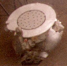
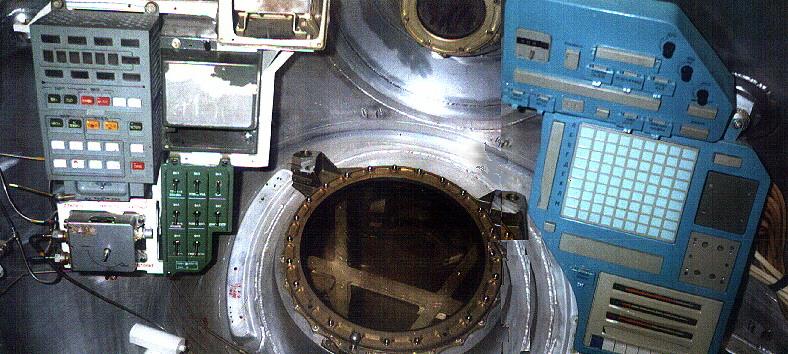
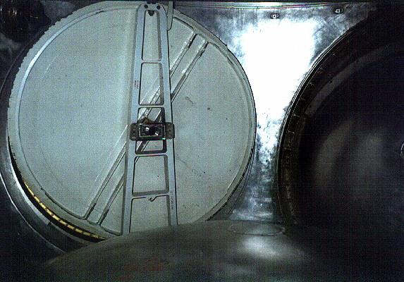
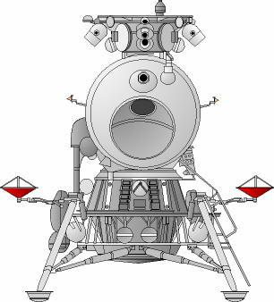
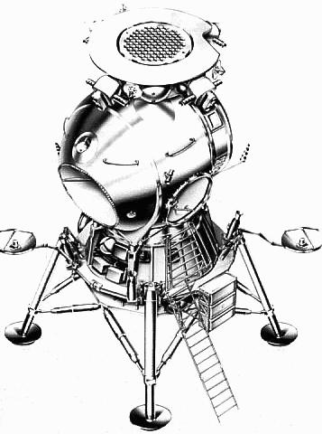 LK Overhead Overhead view of the LK lander, showing Kontakt docking system hexagonal grid docking structure. Exit hatch and ladder are to the right; scallop for main view port at front. Two high gain antennae at either side provided transmission of television from the lunar surface to earth. |
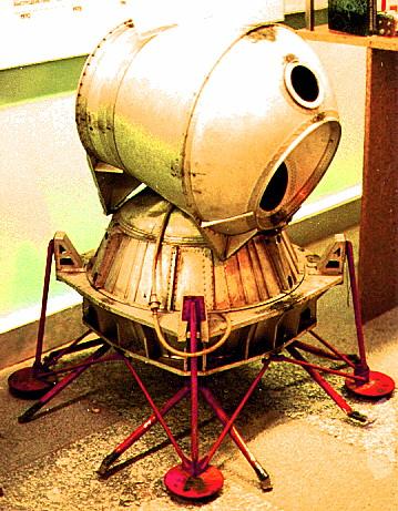
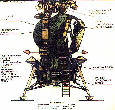
AKA: 11F94;T2K. Status: Operational 1970. First Launch: 1970-11-24. Last Launch: 1971-08-12. Number: 3 . Thrust: 20.10 kN (4,519 lbf). Gross mass: 5,560 kg (12,250 lb). Unfuelled mass: 3,160 kg (6,960 lb). Specific impulse: 315 s. Height: 5.20 m (17.00 ft). Diameter: 2.25 m (7.38 ft).
The LK was to have landed a single Soviet citizen on the moon before the Americans, winning the moon race. It completed development and test flown very successfully in earth orbit, but never reached the moon because the N1 booster required to take it to the moon never had a successful flight.
Because the translunar payload of the Russian N1 rocket was only 70% that of the American Saturn V, the LK differed in many ways from the LM. It had a different landing profile; it was only 1/3 the weight of the LM; it was limited to a crew of one; it had no docking tunnel (the cosmonaut had to space walk from the LK to the LOK lunar orbiter). Unlike the LM, the LK did not use a separate descent stage to go from lunar orbit to landing on the surface. A braking stage, the Block D, took the LK out of lunar orbit and slowed it to 100 m/s at an altitude of 4 km above the lunar surface. From there the LK used the engines of its Block E stage to soft land on the moon. The Block E also served as the ascent stage to return the LK to lunar orbit.
The LK consisted of four primary modules:
- The LPU landing gear, which allowed landing on the lunar surface. The LPU remained behind on the lunar surface, acting as a launch pad for the rest of the LK
- The Block E rocket stage, which soft landed the LK on the moon and returned it to lunar orbit
- The Lunar Cabin, the pressurized semi-spherical cabin where the cosmonaut was located
- The Integrated Orientation System, a pod of small thrusters to orient the spacecraft. Atop the pod was the large hexagonal grid of the Kontakt docking system
Consider now the LK in depth. This article is organized into the following main sections:
- The N1-L3 Lunar Mission Profile
- Development of the LK
- LK Flight Tests
- Technical Description of the LK
The N1-L3 Lunar Mission Profile
On 3 August 1964, Command number 655-268 issued by Central Committee of Communist Party gave Soviet Chief Designer Korolev the objective of putting one man on the moon and returning him safely to earth - ahead of the Americans.
Prior to this, Korolev had concentrated on the earth orbit rendezvous method. His September 1963 L3 design was a 200 metric ton direct-lander requiring three launches of his giant N1 rocket and assembled in low earth orbit. This L3 spacecraft would make a precision 'blind' landing, homing in on a beacon aboard an L2 robotic lunar rover which had already been parked at a suitably flat touch-down point. The 138 metric ton trans-lunar injection stage would propel the L3 spacecraft towards the moon. The 40 metric ton lunar braking stage would ignite 200 to 300 km above the surface. After burnout, it would separate above the surface, allowing the 21 metric ton lunar soft landing/ascent stage, with variable-thrust engines to make a soft landing on the surface. The landing leg structure and soft landing engines would be left behind on the moon. The ascent stage would propel the 5 metric ton Soyuz L1 manned spacecraft back to earth. This capable but expensive spacecraft would have accommodated a crew of three for ten days of lunar surface exploration.
In order to beat the Americans, the redesigned N1-L3 exploited a variant of the Apollo program's lunar-orbit rendezvous method to reach the moon's surface. In this way the mission could be accomplished in just one launch of an improved N1 rocket. The L3 complex designed for the mission, with a total mass of 95 metric tons, would consist of the Block G translunar injection rocket stage; the LOK lunar orbiter; the LK lunar lander; and the Block D deceleration stage.
The N1-L3 lunar flight plan evolved during the course of the program. By the end of LK development it was as follows:
- The L3 complex would be injected into a 220 km, 51.8 degree inclination parking orbit of the earth. Up to one day could be spent in earth orbit before trans-lunar injection.
- The Block G stage was ignited, putting the complex into a translunar trajectory. The Block G then separated.
- During a 3.5 day translunar coast the Block D stage would perform two mid-course corrections. It then would brake the LOK/LK/Block D stack into an equatorial elliptical lunar orbit. The Block D would be restarted twice to adjust the orbit, first to a circular 110 km orbit, then to bring the pericynthion down to 14 km. The Block D could restarted for up to 4 days in lunar orbit.
- The LK pilot would spacewalk from the LOK to the LK and check out the lander and Block D systems.
- The LK/Block D then separated from the LOK. The LK was capable of 72 hours of autonomous operation, 48 hours of which would normally be on the lunar surface. As it approached the landing site, the Block D began its main burn and braked the LK from to 100 m/s at four kilometers above the lunar surface. (Later in development this was reduced to 1.5 to 2.0 km above the surface). The Block D then separated and crashed on the moon about 4 km from the separation point.
- The landing radar acquired the surface at an altitude of 3000 m. The LK's Block E stage then ignited its engines at full 2,050 kg thrust until vertical velocity reached zero. The engine was then throttled back to 850 kgf hover thrust and maneuvered to a soft landing on the surface. Propellant allowance for the whole maneuver was 280 kg, which allowed about 50 seconds hover time to divert to an alternate landing point up to 100 m away from that originally selected by the automated system. Later in development there was less than a minute total for the landing maneuver, including only 15 to 20 seconds of hover time.
- Four hours would be sent in surface operations on the first landing. The cosmonaut would exit the LK to the lunar surface. The space suit was limited to 1.5 hours on the surface at a time. The first Soviet space walk was to consist of: planting the flag; deployment of a very limited array of scientific instruments; taking soil samples; photography of the landscape; and cosmonaut commentary on the lunar surface. The LK could spend a total of from six to 48 hours on the lunar surface on later flights.
- After returning to the LK's Lunar Cabin, the cosmonaut would seal the lunar samples in a hermetic container and then repressurise the cabin. The LK Lunar Cabin and Block E ascent stage would then take-off from the LK landing gear (LPU) and fly back into lunar orbit. The LOK orbiter would rendezvous and dock with the LOK using the 'Kontakt' system. The LK cosmonaut then space-walked from the LK back to the LOK with the lunar samples. The LK was then cast off.
- After up to one additional day in lunar orbit, the LOK's Block I engine would put the LOK into trans-earth trajectory. 3.5 days was to be spent on the coast back to earth with two midcourse corrections en route. Before re-entry, the descent module separated from the LOK with the two cosmonauts aboard. It re-entered the earth's atmosphere over the South Pole at 11 km/sec, skipped back out to space after slowing down to 7.5 km/s, then soared 5,000 km before making final re-entry and landing on the territory of the USSR.
Development of the LK
The N1-L3 project was too big for one enterprise. Korolev's OKB-1 was assigned general management of the project. V M Filin was named manager for the LK within OKB-1. However detailed design, qualification, and construction of the LK Block E engine system was subcontracted to Yangel's OKB-586 in Dnepropetrovsk, Ukraine.
The advance design project for the N1-L3 was completed on 30 December 1964. The decree for production of 16 shipsets of spacecraft and boosters was issued on 26 January 1965. The N1-L3 was to manufactured to the following schedule: 4 in 1966; 6 in 1967; and 6 in 1968. The plan was for the first launch of the N1 to be in the first quarter of 1966, with the first lunar landings in 1967 to 1968, ahead of the American goal of 1969.
But as soon as detailed design of the LK began it was realized that the mass of the spacecraft in the draft project was completely unrealistic. The young engineers that had done the preliminary LK design had made numerous absurd assumptions. They had assumed a soft landing delta v of only 30 to 40 m/s (200 to 300 m/s was a more realistic estimate). A thirty degree braking angle was assumed after separation, but at this angle the radio altimeter couldn't detect the surface. Such optimistic assumptions resulted in the draft project putting the mass of the LK at 2 metric tons, with a crew of two. (The final LK would have a mass of 5.5 metric tons and be able to accommodate only one cosmonaut!)
Still, Yangel wanted to be sure to leave room for a crew of two in the cabin. But it was quickly discovered that this simply could not be done within the 40 to 50 metric ton low earth payload allotment for the LK/Block D. Given the original mis-estimate, throughout the project weight reduction was a constant concern. A separate descent stage would have had greater economy, but this presented numerous other problems not well understood when the project started. The Chief Designers offered prizes of 50 to 60 rubles per kilogram of weight reduction identified by project engineers. 500 kg was saved just by optimizing the rendezvous orbit.
The capability and accuracy of the landing radar system was the crucial first problem in development. The prompt and precise determination of the velocity and altitude of the LK after separation from the Block D was the key to minimizing propellant usage for the landing and determined the sizing of the whole LK vehicle (due to the propellant reserves required for touchdown and hover maneuvers).
The landing radar system was designated Planeta. Planeta consisted of four antennae, with their beams arranged in an asymmetric pyramid. Three determined the velocity vector using Doppler, while the fourth beam, in the central position, determined altitude above the surface. The system was simple and reliable. It was later proven on the Luna Ye-8 automated lunar sample return probes.
Numerous problems had to be solved regarding the reflection of the radar beam from the surface - problems analogous to those tackled a decade later in America in the design of stealth aircraft. Tests of the Planeta system aboard MiG-17 aircraft indicated that the initial radar reflectivity assumptions were wrong by several orders of magnitude.
Ignition of the Block E stage was commanded automatically by the Planeta system when the LK was 3 km from the touchdown point. After eliminating the vertical velocity, the final landing maneuver was commanded by the cosmonaut. Landing was made in the deep throttle range of the Block E. Engine shutoff was commanded automatically by the Planeta system.
OKB-1 Chief Designer Mishin allowed only a 280 kg propellant reserve for the entire landing maneuver. This constraint prolonged development of the Planeta system. In 1967 Yangel finally went to the Chief Designer's committee and informed them that he could not meet the requirement for two complete lunar landers until 1971.
In 1968 the L3 scheme was overhauled. The original scheme had assumed a landing on the lunar equator. This meant that the LOK orbiter would pass over the landing site once per orbit, every hour. For the ascent of the LK to the rendezvous orbit in this case, a simple gyroscopic platform could accomplish the launch, as was used on the V-2 and R-7 missiles.
At landing sites away from the equator, within two to three orbits the LOK orbital plane would move too far away from the landing site to make such a pre-programmed ascent into the rendezvous orbit. Therefore a new type of guidance system was required. There were three possible choices:
- Install a full-capability inertial navigation unit. This would allow the LK to perform a complex dog-leg maneuver during ascent to reach the plane of the LOK orbit (this was the American LM solution)
- Use a strap-down gyroscopic platform to steer the LK in a pre-programmed deviation from its vertical axis until the LOK orbital plane position was reached.
- Use the existing platform but develop a pre-set program of yaw angles, set before launch.
A major difficulty during development was getting the cabin center of mass on the thrust axis. It could not deviate more than 30 mm from the thrust axis or stable flight of the LK would not be possible. This requirement dictated the design of the propellant tanks of the Block E stage and Integrated Orientation System; required the development of special restraints for the cosmonaut in the cabin; and dictated the placement of equipment on the exterior of the LK. In particular the location of the heavy batteries was continually shifted during development.
LPU Development
The LPU - lunniy posadocnie ustroistviy - was the landing leg assembly of the LK. It would remain behind on the surface, acting as a launch pad for the Block E rocket stage. .Therefore the LPU not only to had to absorb the shock of landing, but provide a level base for the ascent stage as well. All systems not necessary for ascent were attached to it. A A Sarkisyan was in charge of LPU design.
The overall LK mass problem meant that there was only sufficient reserve propellant to move no more than 100 m from the original landing point selected by the automated system. Studies of Ranger photographs of the lunar surface indicated that the 100 m requirement meant that it was most likely the LK would land in a crater of 7 m diameter. This translated into the specification that the LPU be able to handle slopes of 30 degrees with the LK center of gravity being 2.5 m above the surface. The requirement for high confidence unmanned landings also played a role in the stiff requirement.
The minimum design, as used on the US Surveyor, was three legs. But a three legged craft would require double the span of a four legged design for the same stability, and could not meet the thirty degree slope requirement. The design of the LPU was such an 'interesting' engineering problem that engineers from many sections of OKB-1 and Yangel's bureau proposed solutions. In the end over twenty variants of LPU landing gear layouts were studied, including toroidal rings, within which the LPU equipment would be housed, and some bizarre water-stabilized designs.
Many of these ingenious approaches were too complex and mechanically risky. Finally V H Shaurov conceived the idea of 'nesting' engines - engines that would fire DOWNWARD at the instant of touchdown to remove all tipping moments from the spacecraft. This 'active' method of touchdown would reduce the complexity of the gear themselves while meeting the 30 degree requirement. In the end two gear schemes - passive (Feoktistov) and active (Shaurov) - were studied using scale models. Volcanic tuff believed to resemble the lunar regolith was imported from Armenia to simulate the lunar surface. A 300 x 400 mm sand pit was modeled with the tuff, including craters. The tests proved the active system, which was used on the LK.
A full scale mock-up of the final LPU design was built and tested. The shock absorbing techniques developed for the LK gear were later used in the androgynous APAS docking systems developed for Apollo-Soyuz and Mir. Kiselev proposed additional development of an altimeter-triggered soft landing rocket to cancel all vertical velocity, as was done for earth landings of the Soyuz system. But there was no time to develop the system.
Mounted on the LPU were those systems not required after the landing on the moon: the landing altimeter, parabolic antennae, chemical batteries, and three water tanks for the evaporative cooling system (a fourth was added late in development to trim the center of gravity).
Lunar Cabin
A cabin environment using pure oxygen at 0.40 atmospheres was considered, but the need to develop special armatures, fire-proof materials, and the safety of the cosmonaut resulted in this being rejected. So the cabin environment selected was air at 0.74 atmospheres. This meant the cabin pressure vessel had to be twice as heavy, but this was considered worth it from a crew safety point of view.
Soviet experience in manual control of spacecraft was limited at the time of LK development. The development team had to return to first principles in determining the control layout and the position of the cosmonaut. The challenging requirements included the need to operate the controls in a pressurized space suit in the event of cabin depressurization. Therefore foot pedals couldn't be used as in a fixed wing aircraft or helicopter. The design team consulted with helicopter and VTOL specialists at aviation design bureaus to solve these problems.
Development of the correct arrangement and placement of cabin control panels and windows was a long trial-and-error process. It was determined that the optimum viewing angle downwards for landing was 7 degrees. This lower view port was equipped with a collimator for predicting the landing point.
The Kretchet spacesuit developed, the ancestor of those still used on Mir today, could be entered through a hatch in the back. There was an elaborate system of braces and tie-down strips to fix the cosmonaut in a standing position during spacecraft maneuvers. This was because it was necessary to keep the center of mass of the cosmonaut on the thrust axis of the engine.
Ingress/egress development was conducted again by trial-and-error, using full-size LK and suit mock-ups. It was found that the standard hatch developed for the Soyuz orbital module was too narrow for the cosmonaut in the lunar suit. So a special oval hatch had to be developed. This was a controversial solution but was finally approved. The asymmetric mass of the cosmonaut's ladder had to be balanced by placement of equipment on the other side.
Due to weight considerations, no automatic docking system could be considered, as was used on the Soyuz spacecraft. The system objectives were minimum weight, manual operation, and tolerance to low accuracy docking. Since the cosmonaut would spacewalk from the LOK to the LK and back, no hard dock system, with system connections and a hermetic seal between the spacecraft, was required. The Kontakt system that was developed used a snare-like probe on the active LOK spacecraft. The LK was the passive vehicle, and was equipped with a 1.8 meter diameter, lightweight hexagonal alloy grid. Each of the 108 hexagons was a potential receptacle for the LOK's docking probe.
The Kontakt system was to have been tested on a series of earth orbit test flights using Soyuz spacecraft. These were postponed as continued N1 launch failures pushed the date of any possible lunar mission further and further back. In April 1969, two separate docking missions were planned for late 1969/early 1970. After Apollo 11's successful lunar landing, the development and launch of the Salyut space station (to beat the American Skylab) took priority. By December 1970, Kontakt missions were scheduled only after Salyut was successfully flown. Kontakt development was finally terminated in October 1971.
Block E Development
Originally development of the Block E landing/ascent stage was considered the pacing item in LK development. Drawings for the Block E were already issued in parallel with the draft project. The original specification of 510 kg empty mass for the stage could not be met. There were constant mass allocation fights between the rocket block design team and the cabin design team.
The LK variable-thrust, restartable engines represented a huge engineering development task. Unusually, Yangel decided to develop the system within his own OKB rather than entrust it to one of the traditional engine design bureau. New materials and new mechanical solutions were required to obtain a reliable, safe, redundant, durable engine that could be used over a wide variation of payload mass. In charge of Block E engine development was Ivan Ivanovich Ivanov, known to all as I-Cubed.
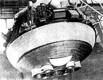
A key problem in design of both the Block E and the LPU was the flow of gases reflected from the surface during touchdown. In Apollo, the descent stage and its engine were left behind on the lunar surface; therefore it did not matter if the descent engine was damaged on landing (as actually occurred several times). But the LK used the same engine for landing and ascent from the surface. A hydrodynamic design had to be found that would prevent any damage to the engines during the landing maneuver. The final approach was streamlined propellant tanks for the Block E, which allowed the gases to flow up and away from the LPU during landing. The Block E engines were also equipped with clamshell doors, which closed at engine shut-off and prevented damage from foreign particles while the LK was on the lunar surface.
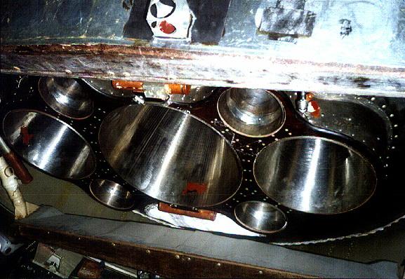
The propellant tanks were of unusual form. There were not only external gas flow considerations, but their geometry had to be specifically designed to keep the center of mass within limits during the landing and ascent to orbit. Since the oxidizer was consumed at twice the rate as the fuel, the geometry had to accommodate this fact. Numerous tank layouts were studied before the optimum compromise between geometry and minimum mass was achieved. The self-igniting storable N2O4/UDMH propellants were stored in nested tanks of identical 1.2 cubic meter volumes.
Integrated Orientation System
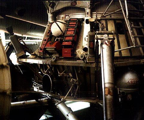
The Integrated Orientation System was mounted above the Lunar Cabin. Yangel had no experience in microthrusters, so development of this system was subcontracted to Isayev. The same N2O4/UDMH propellant combination was used as in the Block E. The forward mounting of the package meant that the installation was 'unclean' - i.e. it introduced not only motion around the center of gravity of the LK, but translation motions as well. The thrusters were arranged in two independent, redundant systems. In each system 2 x 40 kgf thrusters provided pitch; 2 x 40 kgf yaw; and 4 x 10 kgf for roll. Propellant totaling 100 kg was stored in two tanks. The problem arose how to preserve the center of mass of the module on the main thrust line of the LK. The solution was to enclose the oxidizer tank within the propellant tank in a double-walled barrel construction.
The thrusters were pressure-fed using internal diaphragms. This was the first use of such a technique in Soviet spacecraft, and a new steel alloy was developed by Stepanov for the purpose. The tanks were pressurized to 10 atmospheres by helium gas. Operation of the thrusters for continuous periods of up to ten seconds required development of new materials for the nozzles - niobium and graphite. Minimum thrust impulse was as lows as 9 milliseconds. The nozzles were canted 20 degrees from the horizontal when studies revealed that 95 out of 100 times a straight-through design would lose propellant after engine shutoff. This resulted in a mass savings to the LK of 12.5 kg.
LK Development
When the final drawings were reviewed, there was a major fight between the Yangel and Korolev bureaus over a 12 kg 'deficit' in the computed total mass out of the five metric ton total. Korolev's bureau used this to put the entire design into question. After frantic study, the difference was traced to calculation involving the inert gas used for propellant tank membrane pressurization.
Vibration and environmental tests were conducted on equipment at selected stages of fabrication and assembly. Flight tests were conducted of some components.
Military engineering experts from the Baikonur Cosmodrome had to review the design in order for it to be cleared for use at the launch site. They were experienced in missiles and could not understand the unpressurised operation of some of the equipment in a vacuum, the lack of aerodynamic fairings for cable runs, missing shrouds around the cables, etc.
Mock-ups and test stands used in LK development included:
- Egress procedures mock-up. This was the first LK mock-up
- Electrical test stand ('iron bird') to confirm logic and algorithms for control systems.
- Electrical mock-up
- Environmental test mock-up of Block E. This was tested in special vacuum / insolation environmental chambers. It was also used in heat balance studies.
- Mock-up for antenna tests
- Three Block E's for firing tests
- Design of the landing system and cosmonaut training were accomplished on a specially-equipped Mi-4 helicopter, special test stands, and various partial task simulators.
LK Flight Tests
The T1K and T2K versions of the LOK and LK, respectively, were designed for independent earth orbital flight tests of the spacecraft. The T1K was to be launched by Proton and the T2K (also designated LK6/T2K ) by the Soyuz launch vehicle. This special 11A511L version of the Soyuz booster was equipped with a strengthened upper stage and bulbous fairing to accommodate the LK. An entire separate development team under Yu M Labutin was required to develop the special systems necessary for unmanned earth orbit test operations. 20 such systems were used on the T2K, including modifications of those developed for the Soyuz spacecraft. The Labutin team also had to decide what systems could logically be tested in earth orbit and which could not.
Three T2K's were built, in what was envisioned as a three flight program:
Flight 1 - Follow the standard engine profile Flight 2 - Induce or simulate various abort profiles Flight 3 - Reserve in case of failures on Flights 1 and 2
The flight programs were carefully constructed to allow time after each maneuver before the next one would be conducted. This allowed careful measurement of the resulting orbit after each maneuver in order to verify telemetered performance data, as well as time for playback of all telemetry, radio, and television of the events. It was difficult to arrange the schedule within the available LK battery amp-hours.
Inputs that would normally be done by the crew in the landing phase would have to be simulated and commanded from the ground. In order to accommodate the extra diagnostic and telemetry equipment, a second equipment section was installed on the T2K. Unique earth orbit sensors (solar/stellar, ion flow) were installed as well. These were required to orient the LK along the axis of the orbit.
The T2K crews worked day and night preparing the spacecraft, and finally the first T2K was shipped to Baikonur for launch. Each T2K was tested before flight in a vacuum insolation chamber. During vacuum chamber tests at Baikonur, one of the equipment sections decompressed. It was found to have had ten microscopic holes punched into it during transport. These were repaired. Finally fuelled and cleared for launch, the first T2K was launched on a sunny morning in November 1970. The three tests of the T2K went of without a hitch:
- 1970-11-24 - Cosmos 379 - T2K s/n 1: In demonstration of lunar landing and ascent maneuvers, first went from 192 km x 233 km orbit to 196 km x 1206 km orbit, with a delta V of 263 m/s representing the hover and landing maneuver after separation from the Block D. It them simulated the ascent maneuver to lunar orbit, going from a 188 km X 1198 km orbit to a 177 km X 14,041 km orbit with a delta V of 1,518 m/s.
- 1971-02-26 - Cosmos 398 - T2K s/n 2 - Second LK moon lander test using T2K version. Maneuver Summary: 189 km x 252 km to 186 km x 1189 km orbit, delta V 251 m/s; 186 km x 1189 km orbit to 200 km x 10,905 km orbit, delta V 1320 m/s.
- 1971-08-12 - Cosmos 434 - T2K s/n 3 - Final LK moon lander test using T2K version. Maneuver Summary: 188 km x 267 km orbit to 190 km X 1261 km orbit, delta V 266 m/s; 188 km x 1262 km orbit to 180 km X 11,384 km orbit, delta V 1333 m/s.
A two-crew version of the LK was studied for support of the Zvezda DLB lunar base planned after the initial landings. Space was so limited that special recesses would have to made in the cabin wall to accommodate the helmets of the two suited cosmonauts. However this was a moot point, since the increased payload required major modifications of the engines and propellant tanks, which were specifically designed for the single-crew, 5,500 kg LK. In the end it was decided that this was not practical. Larger lunar landers were instead designed by Korolev's bureau using Soyuz return capsules and descent stages copied from the American lunar module layout.
Yangel died soon after completion of the successful T2K flights, content that he had done his part for the program.
LK landers are preserved at the MAI museum in Moscow (this was a flight model that was displayed at Eurodisney in 1997), the MAI museum at Orevo (an engineering article), St Petersburg, the Energia plant at Korolev, north of Moscow, and at KB Yuzhnoye in the Ukraine.
Description of the LK
At the end of development the LK as designed had a mass of 5,560 kg, with the Block E stage weighing 2,950 kg. Takeoff mass from the lunar surface was 3,800 kg. The total height was 5.2 m. As with most aerospacecraft, the LK must be looked at from both a systems and a module viewpoint.
LK Modules
LPU
The LPU - lunniy posadocnie ustroistviy - was the landing leg assembly of the LK. The LPU was able to handle slopes of 30 degrees with the LK center of gravity being 2.5 m above the surface. Solid propellant 'nesting' engines fired downward at the instant of touchdown to remove all tipping moments from the spacecraft. Mounted on the LPU were those systems not required after the landing on the moon: the landing altimeter, parabolic antennae, chemical batteries, and three water tanks for the evaporative cooling system (a fourth was added late in development to trim the center of gravity). A video camera was externally mounted to give the ground a view of surface operations. It may be calculated from data given that the LPU, with its associated equipment, had a total mass of about 1,440 kg (5,560 kg LK mass - 280 kg descent propellant - 40 kg orientation system propellant used during descent - 3800 kg given as LK mass at start of ascent).
Block E Rocket Stage
The streamlined shape of the Block E allowed engine exhaust gases reflected from the lunar surface to flow up and away from the LK during landing. The Block E engines were equipped with clamshell doors, which closed at engine shut-off and prevented damage from lunar soil while the LK was on the lunar surface.
Total Block E mass has been given as 2,950 kg. It was stated that the original specification of 510 kg empty mass for the stage could not be met; assuming a 10% weight growth during development, the empty mass was probably around 550 kg. This would give a propellant load of 2,400 kg (volumetric capacity of the 2 x 1.2 cubic meter tanks was 2,600 kg). Propellant consumption in the landing maneuver was 280 kg, leaving about 2,100 kg for the ascent into orbit. The engines were rated to burn up to 2,900
Crew Size: 1. Orbital Storage: 30 days. Habitable Volume: 5.00 m3. RCS Coarse No x Thrust: 4 x 390 N. RCS Fine No x Thrust: 4 x 98 N. RCS total impulse: 245 kgf-sec.
More at: LK.
| LKR Russian manned lunar rescue spacecraft. Version of the LK that would act as a reserve spacecraft in a two-launch scenario. The LKR woud allow return of the cosmonaut to lunar orbit in the event of failure of the primary LK lander. |
Family: Lunar Landers, Moon. Country: Russia. Engines: RD-858. Spacecraft: L3, DLB Lunar Base. Launch Vehicles: R-7, N1, Soyuz 11A511L, N1 1969. Propellants: N2O4/UDMH. Projects: Lunar L3. Launch Sites: Baikonur, Baikonur LC31. Agency: Korolev bureau, MOM. Bibliography: 123, 125, 164, 165, 168, 184, 2, 21, 23, 367, 376, 474, 6, 72, 75, 11340, 12762.
 | LK Landing Profile Landing and abort profile of the LK lander. Credit: © Mark Wade |
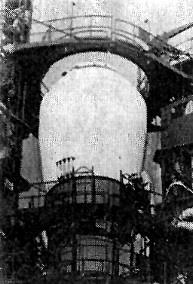
 | LK Credit: Manufacturer Image |
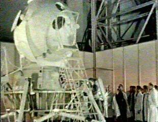
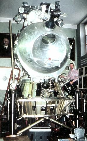
 | LK Overall view of the LK preserved at the Orevo Museum of the Bauman Moscow State Technical University. Credit: © Mark Wade |
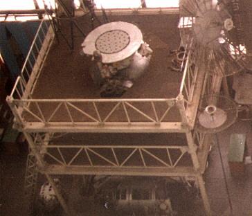
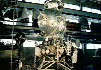 | LK Lunar lander LK lunar lander in assembly hall. Credit: RKK Energia |
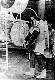
 | LK egress tests Numerous tests were conducted to determine the best hatch and ladder configuration for the cosmonaut in the bulky Kretchet spacesuit. It was found the standard Soyuz hatch had to be replaced by a customized oval hatch. Credit: RKK Energia |
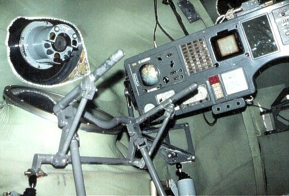
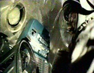 | LK Interior Rare view of suited cosmonaut in the interior of the LK Interior during landing training. The cosmonaut had a viewing angle to the surface through the main window of 7 degrees from the vertical. A collimator indicated the predicted LK landing point. Credit: RKK Energia |
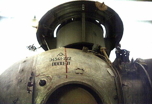
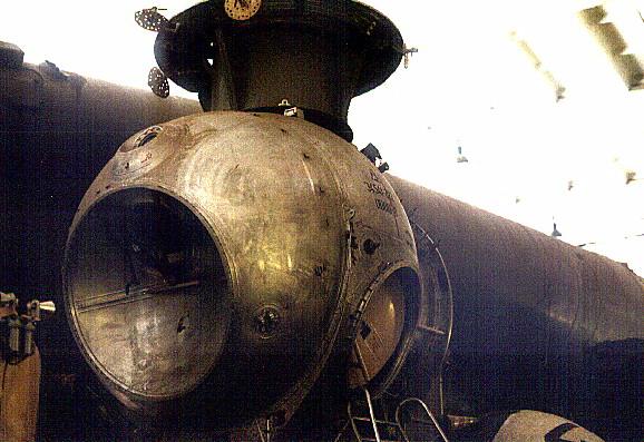
 | Top of LK at MAI MAI, March 1994 Credit: © Dietrich Haeseler |
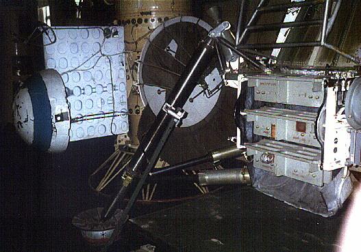
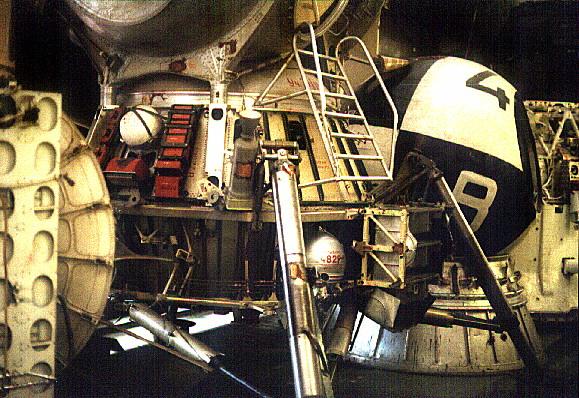
 | LK at MAI in rig MAI, March 1994 Credit: © Dietrich Haeseler |
 | T2K in Shop |
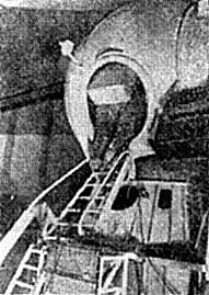
 | LK First Mockup Early egress tests in the very first LK mock-up. This mock-up shows the earlier configuration of the lunar cabin, Block E landing / ascent stage, and LPU landing gear. |
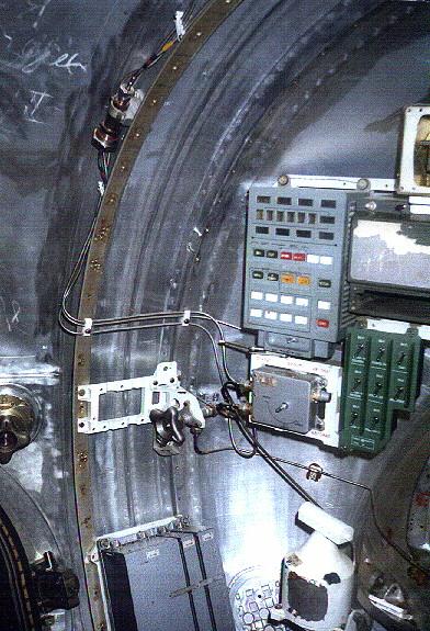 | LK interior left View of the LK interior to the left of the cosmonaut, showing the cabin depressurisation control panel, the radio control panel, cabin depressurisation valve, and the edge of the exit hatch to the left. Credit: © Mark Wade |
 | T2K Shroud on Pad |
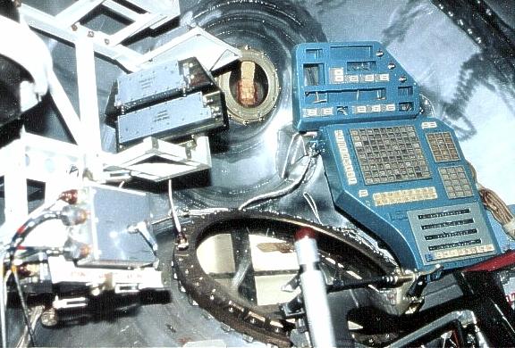
 | LK interior right View of LK interior to the right of the cosmonaut. The large viewport provides good visibility for the piloted descent to the lunar surface. The smaller viewport is for use in rendezvous and docking with the LOK lunar orbiter. Pre-programmed sequences were called up on the blue sequencer master panel, with guarded switches for initiating major engine burns and explosive events. Environmental control system box at left provides connections to the cosmonaut's Krechet space suit. Credit: © Mark Wade |
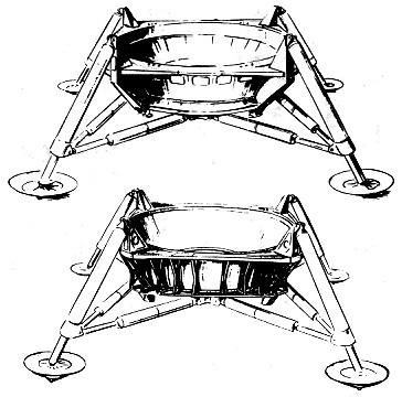
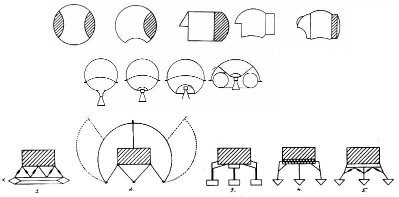 | LK Evolution Steps in evolution of the LK lunar lander. Top row, from right to left: development of the Lunar Cabin progressed from a simple sphere housing a seated cosmonaut with separate twin equipment sections, to a single equipment section, then finally to the complex shape with separate equipment module required to provide good visibility for landing and docking. Middle row: Development of the Block E landing/ascent rocket stage was dictated by the requirements of minimum weight, symmetric depletion of the propellant tanks, and an aerodynamic shape to deflect exhaust at landing away from the engine bell. Bottom row: alternate LPU landing gear approaches considered. From left: toroidal landing ring, housing LPU equipment; wild landing bag/water stabilised approach; variants on conventional gear. |
 | LK LPU-Draft & Final Detailed design of the LPU landing gear. At the top: design at the stage of LK draft project. At the bottom: the final production design. |
 | LK interior back View of the LK behind the cosmonaut. Environmental control, cooling, and electrical connections snake around the cabin. The round connection port to the left provides connection of interior service lines to the exterior cable/line bundle. The large round aft cover goes to the instrument section mounted to the rear of the spherical LK cabin. Credit: © Mark Wade |
 | LK Landing Tests A subscale model of the LK's LPU landing gear were used in tests to verify the use of 'nesting rockets' - downward-firing motors that would plant the lander firmly on the surface at slopes of up to thirty degrees. Credit: RKK Energia |
 | T2K Cabin |
 | LK Crew Station A view of the actual fully-equipped LK crew station. Significant equipment is present that is not in the mock-ups that can be viewed today. Note the collimator/aiming reticule over the landing viewport; the cabin crowded with pilot restraints, pipes, and equipment racks. It is clear why accommodation of more than one cosmonaut in this space was not feasible. |
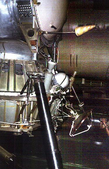
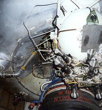
 | LK LPU View of the LK Block E to the right of the cosmonaut ladder. The blue antenna is part of the landing radar system. The instruments for this were mounted in a globular housing (missing on this mock-up) mounted on the aluminium struts. These would have been left behind with the landing platform when the LK ascended to lunar orbit. Tanks for oxygen and water are arranged around the LPU in a manner to ensure the centre of gravity of the LK remains on the thrust axis. That's the fin of a Scud missile in the foreground. Credit: © Mark Wade |
 | LK Egress Tests Another view of LK egress tests. This view makes clear the large size of the backpack of the Kretchet suit and the tight squeeze getting into and out of the LK lander. Credit: Filin |
 | LK panels The cosmonauts' view of the LK viewports and control panels. On the left, environmental control and cabin depressurisation controls (light blue panel); radio controls (dark green panel); large porthole looking down at lunar surface during landing. The small porthole looked upward for docking. The optical devices that were associated with these portholes are not present in this mock-up. To the right, sequencer panel for calling up sequences for manoeuvres, landing, rendezvous, and docking. Guarded switches initiated major events. One of two hand controllers is visible below the green radio panel. Credit: © Mark Wade |
 | LK IOS View View of the LK Lunar Cabin and the Integrated Orientation System at the top of the cabin. Note the angled position of the main thrusters, the omni directional 'carrot' antenna at the lower right, and the hexagonal housing of the solar/stellar sensors at the upper right. |
 | LK at Korolev Large size photo of the production LK. Note the Vzor optical device fixed to the upward-looking porthole, which allowed the cosmonaut to determine and command attitude, range, and range rate information for docking with the LOK lunar orbiter. |
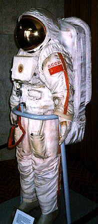 | Krechet Spacesuit Krechet lunar space suit as displayed at NPO Zvezda. As in the Orlan suit still used on Mir, the cosmonaut entered the suit by swinging open a hatch at the rear. The backpack containing the life support system was housed in the backpack which made up the hatch door. As in Apollo, the gold-coated outer visor of the helmet reflected ultra-violet radiation. The integrated Kretchet design meant that no external hoses were required as in the American Apollo suit. Credit: Andy Salmon |
 | Krechet Spacesuit Front view of the Krechet lunar space suit Credit: Andy Salmon |
 | LOK-LK Drawing Unusual alternate diagram of LOK and LK lunar craft in docked configuration, with bottom view of LK. Korolev School. Credit: Jakob Terweij |
 | LK Base / Korolev Close-up view of the engines of the LK exhibited at Korolev School. Credit: Jakob Terweij |
 | LK Interior-Korolev Interior of the an unknown LK also exhibited at Korolev school. This has partially-installed lunar landing instruments. Credit: Jakob Terweij |
 | LK at Korolev LK exhibited at Korolev School. Note the optical device on the upper porthole, part of the semi-automatic optical docking system. This is not seen on other LK's exhibited. Credit: Jakob Terweij |
 | LK Interior-Korolev Interior of the LK exhibited at Korolev school. Note the optical device on the upper porthole, part of the semi-automatic optical docking system. This is not seen on other LK's exhibited. Otherwise this LK seems to be equipped with earth-orbit systems of the T2K, rather than the lunar landing system panels. Credit: Jakob Terweij |
 | LK Test Article Subscale dynamic test article of a late configuration of the LK, as preserved in the TsniiMash museum. This shows well the complex shape of the Lunar Cabin and the final LPU configuration. Credit: © Mark Wade |
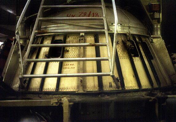
 | LK interior hatch View of the LK exit hatch. This is a simplified representation of the real hatch. Note the spherical bulkhead that forms the floor of the LK. Credit: © Mark Wade |
 | LK landing leg View of the LK leg to the left rear of the cosmonaut. Note the solid fuel nesting rocket mounted at an angle to the gear strut. Credit: © Mark Wade |
 | LK Block E The Block E landing/ascent stage of the LK, viewed separately from the LPU landing gear. Note the clean aerodynamic shape and the engine guards, necessary to divert exhaust gases and debris away from the engine nozzle during landing. |
 | LK base View of the base of the LK, below the ladder coming from the hatch. Credit: © Mark Wade |
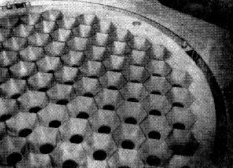 | LK Kontakt Dock Grid The LK was normally the passive vehicle in docking with the LOK. Atop the LK was this grid of 108 hexagonal holes, each a potential docking port for the snare docking probe of the LOK. This system allowed docking to take place without precision alignment of the two vehicles. |
 | LK aft view View of the aft of the LK behind the cosmonaut. The dish antenna is for beaming of television of the landing back to earth. The conical antenna is for omnidirectional radio communications. A water tank of the cooling system is flanked by the two gear with their nesting rockets. Credit: © Mark Wade |
 | LK Egress Tests Another view of LK egress tests, showing the challenge of squeezing through the LK hatch in the Kretchet suit. |
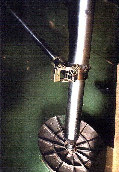
 | LK plumbing Close-up of plumbing at the base of the LPU. This water tank was part of the LK cooling system. The markings indicate a capacity of 25.3 l. Credit: © Mark Wade |
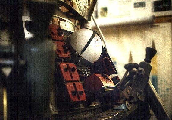 | LK LPU detail Close-up of the LK LPU section to the right of the cosmonaut. The red boxes are mock-ups of electronic black boxes. The oxygen tank and solid rocket nesting motors are clearly seen. Credit: © Mark Wade |
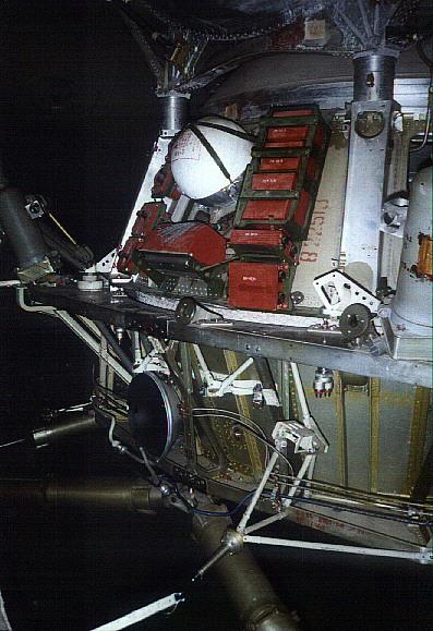 | LK Block E detail Close-up of the LK LPU section to the right of the cosmonaut. The red boxes are mock-ups of electrical / electronic black boxes and batteries. Credit: © Mark Wade |
 | LK Block E Close-up of the side of the LK LPU section behind the cosmonaut. The large antenna would have deployed pointing upward to relay television pictures of the landing and moonwalk back to earth. Credit: © Mark Wade |
 | Early Egress Test Close-up of the earliest version of the Kretchet suit and LK mock-up during egress tests. |
 | LK landing pad Close-up of a landing pad, showing the construction of the strut and the fillets machines into the pad. Credit: © Mark Wade |
 | LK ladder Close-up of the ladder leading to the LK hatch. Credit: © Mark Wade |
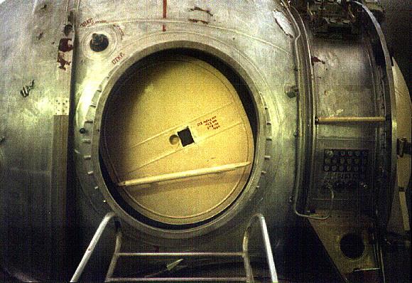 | LK entrance hatch The entrance hatch to the LK lunar lander. On the right is the large instrument section, with connector plates for interior/exterior connection of electrical, electric, and piping services. Credit: © Mark Wade |
 | LK IOS Closeup Close-up view of the Integrated Orientation System block above the exit hatch, topped by the disk-shaped hexagonal mesh platform that the LOK would use to grapple the LK. The top of the instrument section, with the connection plate, is visible on the right. Credit: © Mark Wade |
 | LK ladder base Detail of the base of the ladder, showing the battery racks below the ladder. Note the shape of the foot pad. Credit: © Mark Wade |
 | LK cabin View of the LK cabin with a crude mock-up of the Integrated Orientation System block atop it. The disc antennae around the top of the block are of unknown purpose; possibly part of a radio-locator system to assist in finding the LOK during rendezvous operations. Credit: © Mark Wade |
 | LK landing leg View of the landing leg to the cosmonaut's front left. Note the solid rocket motors mounted above each leg that fired DOWN to settle the LK securely on the surface once the lander was near the surface. These greatly improved the chances of a safe landing. The system could handle landing on a 20% slope or with one leg on a moon rock. The descent ladder is seen coming from the hatch. The box at the base of the latter houses batteries for electric power. Credit: © Mark Wade |
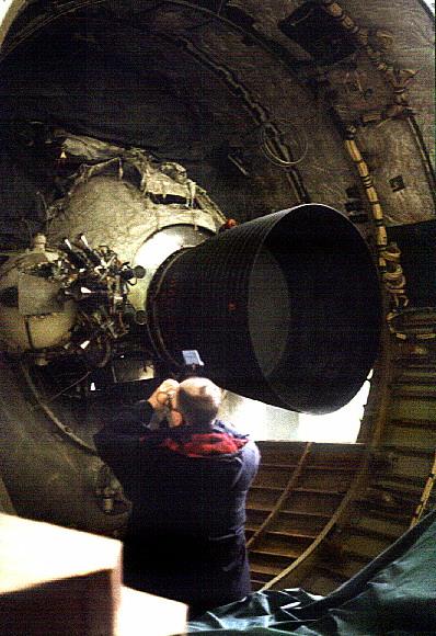
 | LK Main Engine The LK engine cluster at the base of the lander. The single chamber RD-858 of the 2,050 kgf main engine is at the centre. It is flanked by the two nozzles of the RD-859 2,045 kgf backup engine. The smaller nozzles are exhaust nozzles for the turbines of the pump-fed engines. At landing or takeoff, both the primary and backup engines would ignite. Only if both engines were operating, would one shut down. The thick clamshell doors closed over the engines after landing to insulate them and prevent ingestion of lunar soil. Credit: © Mark Wade |
 | LK landing leg View of the landing leg to the cosmonaut's front left. Note the solid rocket motors mounted above each leg that fired DOWN to settle the LK securely on the surface once the lander was near the surface. Yangel OKB tests proved such rockets greatly improved the chances of the rocket not toppling if landing on a 30 degree slope or with one leg on a moon rock. The descent ladder is seen to the right of the picture. Credit: © Mark Wade |
 | LK with Block D LK with Block D Lunar Crasher stage. This is the configuration that would have braked until just above the surface, when the LK would have jettisoned the Block D, extended its legs, and manoeuvred to a soft landing on the surface. Credit: © Mark Wade |
 | Block D / 11D68 Aft view of the Block D lunar crasher stage and its 11D68 engine. The Block D would have taken the LK lunar lander to near the surface of the moon. This stage remains in use today atop the Proton rocket. Credit: © Mark Wade |
 | Engine 11D68 detail Close-up view of the 11D68 Block D lunar crasher stage showing detail of the BOZ orientation/ullage thrusters that control the stage during coast, restart, and manoeuvre. Credit: © Mark Wade |
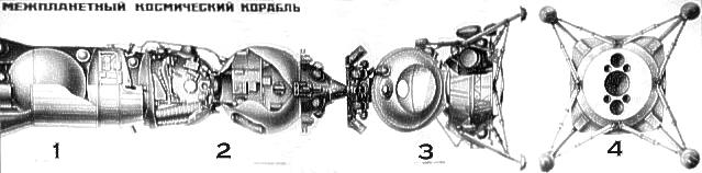
 | Apollo vs N1-L3 Apollo CSM / LM vs L3 Lunar Complex Credit: © Mark Wade |
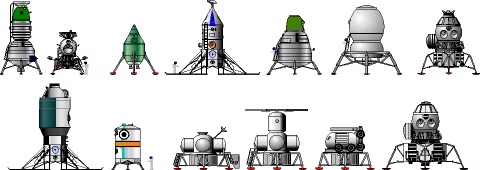 | Soviet Lunar Landers Landing stages for Soviet lunar expeditions. Top row, left to right: L3 original version; LK; LK-3; LK-700; two versions of the L3M; LEK for Energia-launched lunar landing. Bottom row, lunar base elements: Chelomei KLE; Chelomei Heavy Lunokhod; Barmin DLB base module; LZM, LZhM, Lunokhod, and LEK for Glushko LEK Vulkan-launched lunar base. Credit: © Mark Wade |
 | LK Detail forward view drawing of the LK lunar lander. Credit: © Mark Wade |
 | LK Two View Two view layout drawing of LK lunar lander. Credit: © Mark Wade |
 | LK Lunar Lander LK lunar lander. |
 | LK drawing at Kaluga Cutaway drawing of LK lunar lander, showing position of cosmonaut in cabin. Credit: e |
 | LM vs LK US Lunar Module compared to Soviet LK lunar lander Credit: © Mark Wade |
1964 July 19 - .
- Korolev obtains preliminary approval for a single-launch, lunar orbit rendezvous, manned landing. - .
Nation: Russia.
Related Persons: Bushuyev,
Chelomei,
Feoktistov,
Glushko,
Korolev,
Mishin,
Smirnov,
Yangel.
Program: Lunar L3,
Lunar L1.
Spacecraft: L3-1963,
LK,
LK-1,
Soyuz 7K-LOK.
Work on the original N1-L3 had begun in 1963. This had been preceded by two years of working on a draft project for the LK lunar lander and its propulsion system. But there was no money for full scale development -- no code name from Gosplan against which to charge such work. It was annoying that Chelomei, Glushko, and Yangel were wasting resources on alternate designs at the same time. Additional Details: here....
1964 July 21 - . Launch Vehicle: N1.
- Korolev's single-launch lunar scheme reviewed by the Chief Designers - . Nation: Russia. Related Persons: Glushko, Isayev, Keldysh, Khrushchev, Korolev, Kuznetsov, Pilyugin, Smirnov. Program: Lunar L3. Spacecraft: LK, Soyuz 7K-LOK. How to achieve the additional N1 payload was a key point of discussion.. Additional Details: here....
1964 July 27 - .
- Space simulator plans - .
Nation: Russia.
Spacecraft: LK,
LK-1,
Soyuz 7K-LOK,
Soyuz A,
TMK-1,
TMK-E.
A two-day conference is held at IAKM to review requirements for trainers and task simulators over the next 6 to 7 years. The plan includes basic instructional versions of planned spacecraft, trainers for flying around the moon, and a mock-up of the TMK Heavy Interplanetary Spacecraft. These will require a new facility of to 7,000 square metres. Trainers and strands at TsPK will be housed in building D, a hangar-type facility. The TBK-60 thermal/barometric chamber will be housed in a single hangar. To fully specify TsPK trainers and stands for the lunar mission, trainers for space navigation, and military combat spacecraft will not be completed until 1965.
1964 August 1 - .
- Full scale development of Soviet manned lunar flyby and landing projects authorised. - .
Nation: Russia.
Related Persons: Chelomei,
Korolev.
Program: Lunar L1,
Lunar L3.
Flight: Soyuz A-1,
Soyuz A-2,
Soyuz A-3,
Soyuz A-4.
Spacecraft: LK,
LK-1,
Luna Ye-8,
Soyuz 7K-LOK,
Soyuz A.
Central Committee of the Communist Party and Council of Soviet Ministers Decree 655-268 'On Work on the Exploration of the Moon and Mastery of Space--piloted LK-1 circumlunar and L3 lunar landing projects and the Ye-6M lunar lander' was issued. Chelomei was to develop the three-stage UR-500K booster and LK-1 spacecraft for the manned lunar flyby. Korolev was to develop the totally different N1 booster and L3 spacecraft complex for the manned lunar landing. First launch of the N1 was to be by the first quarter 1966, with manned lunar landings in 1967 to 1968. Reprioritization led to work being stopped on Korolev's Zvezda 6-man orbiting weapons platform by mid-1965, after a huge mockup had been built.
Korolev felt that if he had the full support of the Communist Party, the military, and industry he could achieve this goal, and this decree ordered such support. The USSR would be first on the moon. But in truth the draft project behind the decree had not solved all of the technical problems, or provided a solution on how to achieve the required payload on either the booster or spacecraft side. New technology features required for success of the scheme included an advanced guidance system in the N1 third stage equipment bay, the enormous fuel tanks in the N1 first stage, and the Lox/LH2 fuel cells needed for the LOK lunar orbiter. But the real technical problem with the N1-L3 design was the total lack of any weight growth reserve. Even thought the systems had not even been developed yet, engineers were fighting over tens of grams in their weight allocations, let alone the kilograms normally at issue.
Development of Korolev's Soyuz A-B-V, a competing circumlunar project, was evidently still authorised, although it duplicated Chelomei's LK-1.
1964 October 28 - .
- Lunar project orders issued to industry. - . Nation: Russia. Program: Lunar L1, Lunar L3. Spacecraft: LK, LK-1, Luna Ye-8, Soyuz 7K-LOK. Military-Industrial Commission (VPK) Decree 'On assignment of lunar programs to OKB-52 and OKB-1' was issued..
November 1964 - .
- Korolev's admits that N1 cannot attain payload needed for single-launch mission - .
Nation: Russia.
Related Persons: Babakin,
Brezhnev,
Chelomei,
Khrushchev,
Korolev,
Kozlov,
Lavochkin,
Ustinov,
Yangel.
Program: Lunar L3.
Spacecraft: LK,
LK-700,
Soyuz 7K-LOK.
Korolev speaks privately to Chertok. Kozlov has told him it will be impossible to build an N1 with the 93 tonne payload capability until the fourth flight article. The L3 concept was still the same as in the August decree - 2 cosmonauts aboard the LOK orbiter, one aboard the LK lander. Korolev asks Chertok to take 800 kg out of the weight budget for the L3. Chertok informs him that they are already 500 kg over the August budget. This is still without all the unknowns of the automated lunar landing being solved. Additional Details: here....
During 1965 - . Launch Vehicle: N1.
- N1 development issues - .
Nation: Russia.
Related Persons: Korolev,
Pilyugin,
Raushenbakh.
Program: Lunar L3.
Spacecraft: LK,
Luna E-6,
Soyuz 7K-LOK.
There were two camps on the N1-L3 control systems. One group was within OKB-1, and had developed the systems for the Vostok and Zenit spacecraft, under the personal oversight of Korolev. They stressed the maximum quality and reliability in their systems. The second group had worked with Pilyugin, and had designed the systems for the Mars, Venus, Luna E-6 probes, the R-9, RT-1, RT-2, and GR-1 missiles; and piloted spacecraft. Their design emphasis was on maximum usability and output. Pilyugin had been named chief designer of the control system for the N1-L3. Additional Details: here....
1965 February 10 - . Launch Vehicle: N1.
- L3 single-launch spacecraft draft project approved. - .
Nation: Russia.
Related Persons: Keldysh,
Korolev,
Pilyugin.
Program: Lunar L3.
Spacecraft: LK,
Soyuz 7K-LOK.
Interdepartmental Scientific-Technical Council on Space Research (MNTS-KI) Decree 'On approval of the L3 draft project' was issued. The decree followed a review by a Keldysh-led Academy of Sciences state commission the previous December. The decree moved the first flight of the N1 to the end of 1966. Additional Details: here....
Spring 1965 - . Launch Vehicle: N1.
- Guidance system for N1 cannot support planned schedule - . Nation: Russia. Related Persons: Korolev, Pilyugin. Program: Lunar L3. Spacecraft: LK, Soyuz 7K-LOK. By the second quarter of 1965 Pilyugin was already notifying OKB-1 that he could never have the booster guidance system ready for the planned first launch in 1968 - not to even mention the systems for the LOK and LK..
1965 September 1 - . LV Family: N1. Launch Vehicle: N1 1964.
- Voskhod/Soyuz crewing plans - .
Nation: Russia.
Related Persons: Anokhin,
Artyukhin,
Bykovsky,
Gagarin,
Katys,
Kolodin,
Komarov,
Korolev,
Matinchenko,
Nikolayev,
Ponomaryova,
Solovyova,
Volynov.
Program: Voskhod,
Soyuz,
Lunar L3.
Flight: Soyuz 1,
Soyuz 2A,
Soyuz s/n 3/4,
Voskhod 3,
Voskhod 5.
Spacecraft: LK,
LK-1,
Soyuz 7K-L1,
Soyuz 7K-LOK,
Voskhod.
Kamanin meets with Korolev at 15:00 to discuss crew plans. As Soyuz pilot candidates, Kamanin proposes Gagarin, Nikolayev, Bykovsky, Komarov, Kolodin, Artyukhin, and Matinchenko. Korolev counters by proposing supplemental training of a supplemental group of engineer-cosmonauts from the ranks of OKB-1. He calls Anokhin, his lead test pilot, informs Korolev that there are 100 engineers working at the bureau that are potential cosmonauts candidates, of which perhaps 25 would complete the selection process. Kamanin agrees to assist OKB-1 in flight training of these engineer-cosmonauts. Kamanin again proposes Volynov and Katys as prime crew for the Voskhod 3 12-15 day flight. Korolev reveals that, even though Kamanin will have the crew ready by October, the spacecraft for the flight may not yet even be ready by November - Kamanin thinks January 1966 is more realistic. The discussion turns to the female EVA flight - Ponomaryova as pilot, Solovyova as spacewalker. It is decided that a group of 6 to 8 cosmonauts will begin dedicated training in September for lunar flyby and landing missions. Korolev advises Kamanin that metal fabrication of the N1 superbooster first article will be completed by the end of 1965. The booster will have a payload to low earth orbit of 90 tonnes, and later versions with uprated engines will reach 130 tonnes payload. Korolev foresees the payload for the first N1 tests being a handful of Soyuz spacecraft.
1965 September 6 - . Launch Vehicle: N1.
- Problems in lunar projects addressed. - . Nation: Russia. Spacecraft: LK, Soyuz 7K-L1, Soyuz 7K-LOK. Ministry of General Machine Building (MOM) Decree 'On delays in work on piloted lunar programs' was issued..
1965 December 20 - . Launch Vehicle: N1.
- Decision to use analogue guidance in early N1 launches - . Nation: Russia. Related Persons: Keldysh, Korolev, Pilyugin, Ryazanskiy. Program: Lunar L3. Spacecraft: LK, Soyuz 7K-LOK. Pilyugin called Keldysh to tell him he had heard that Keldysh again wanted to form an expert commission to study guidance system development problems with the N1, with Bushuyev as the head.. Additional Details: here....
1965 December 31 - . LV Family: N1. Launch Vehicle: N1 1964.
- Daunting year ahead - .
Nation: Russia.
Program: Voskhod,
Soyuz,
Lunar L1.
Flight: Soviet Lunar Landing,
Soyuz 1,
Soyuz 2A,
Soyuz 7K-L1 mission 1.
Spacecraft: LK,
Soyuz 7K-L1,
Soyuz 7K-LOK,
Soyuz 7K-OK.
Kamanin looks ahead to the very difficult tasks scheduled for 1966. There are to be 5 to 6 Soyuz flights, the first tests of the N1 heavy booster, the first docking in space. Preparations will have to intensify for the first manned flyby of the moon in 1967, following by the planned first Soviet moon landing in 1967-1969. Kamanin does not see how it can all be done on schedule, especially without a reorganization of the management of the Soviet space program.
1966 January 24 - .
- New space schedules - .
Nation: Russia.
Related Persons: Afanasyev, Sergei,
Chelomei,
Korolev,
Malinovskiy,
Petrovskiy.
Program: Voskhod,
Soyuz,
Lunar L1.
Flight: Soviet Lunar Landing,
Soyuz 1,
Soyuz 2A,
Soyuz 7K-L1 mission 1.
Spacecraft: LK,
Soyuz 7K-L1,
Soyuz 7K-LOK,
Soyuz 7K-OK.
The VVS General Staff reviews a range of documents, authored by Korolev before his death, and supported by ministers Afanasyev and Petrovskiy. The schedules for the projects for flying around and landing on the moon are to be delayed from 1966-1967 to 1968-1969. A range of other space programs will similarly be delayed by 18 to 24 months. An institute for tests of space technology will be established at Chelomei's facility at Reutov. The IMBP will be made the lead organization for space medicine. Responsibility for space technology development will be moved from MOM to 10 other ministries. 100 million roubles have been allocated for the establishment of new research institutes. Kamanin is appalled, but Malinovskiy favours getting rid of the responsibility for these projects. The arguments over these changes - which reduce the VVS role in spaceflight - will be the subject of much of Kamanin's diary over the following weeks.
1966 February 17 - .
- Soviet Lunar Landing Plans - .
Nation: Russia.
Program: Lunar L3.
Flight: Soviet Lunar Landing.
Spacecraft: LK,
Soyuz 7K-LOK.
Kamanin presents his plan to train 5 to 6 crews for the lunar landing mission over a 30 month period. Only experienced cosmonauts, with prior spaceflight experience, will be assigned to these crews. Kamanin lays out for the VVS leadership the complex series of events the cosmonauts will have to complete in the L3 lunar-orbit rendezvous scheme, including transfer between spacecraft of a single lunar landing cosmonaut in free space in lunar orbit. Crews need to be formed immediately, with two cosmonauts per crew - the L3 mission commander, and the second cosmonaut who will land on the moon. In order to accomplish the mission on schedule, a new air regiment needs to be formed, with the necessary flying laboratories, simulators and trainers, space suits, test stands and surface simulators, and other equipment necessary to train the crew for the mission.
1966 March 6 - .
- Soviet design bureaux reorganised and renamed. - .
Nation: Russia.
Related Persons: Afanasyev, Sergei,
Mishin,
Okhapkin.
Spacecraft: LK,
Soyuz 7K-L1,
Soyuz 7K-LOK,
Soyuz 7K-OK.
Decree 'On renaming OKB-1 as TsKBEM and OKB-52 as TsKBM' was issued. In 1966 Afanasyev reorganised the military industrial complex. OKB-1 was redesignated TsKBEM. Sergei Osipovich Opakhin was made First Deputy within the new organization.
However within TsKBEM there were no relative priorities for the projects competing for resources. The R-9 and RT-2 ICBM's, the orbital, circumlunar, and lunar orbiter versions of Soyuz, the LK lunar lander, the N1 booster -- all were 'equal'. It seemed folly to be pursuing the orbital ferry version of the Soyuz when no space station had to be funded. But it was felt flying the spacecraft would solve reliability questions about the design, so it was pursued in parallel with the L1 and L3 versions.
1966 May 11 - . Launch Vehicle: N1.
- Mishin selected as Korolev's replacement after four-month delay - .
Nation: Russia.
Related Persons: Babakin,
Keldysh,
Khrushchev,
Korolev,
Mishin,
Mozzhorin,
Okhapkin,
Ustinov.
Program: Lunar L3,
Lunar L1.
Flight: Soyuz 1,
Soyuz 2A.
Spacecraft: LK,
Soyuz 7K-LOK.
From 1963-1965 Ustinov was both head of the Soviet for the National Economy and the First Secretary of the Presidium of Soviet Ministers. He supported civilian space projects and instructed the military to co-operate in them. But after Khrushchev was ousted, Ustinov had less influence with the Ministry of Defence.
After the death of Korolev in January, a letter was sent to the Central Committee requesting that Mishin be appointed director of OKB-1. Ustinov tried to line up support for Mishin, but by the time of the first first Saturn IB orbital flight on 26 February 1966, no decision had been made. America was progressing on the path to the moon, but Russia was stalled. An alternate that had been considered was Sergei Okhapkin, another Deputy Chief Designer at TsKBEM. But Okhapkin knew only spacecraft, he had never developed complete launch-booster-spacecraft systems. By the time Mishin was appointed, it was clear that the race was lost. The American's planned their first Saturn V launch in September 1967 and their first manned flight in 1968. Mishin could not expect trials of the LK lunar lander until 1969 at the earliest. There were insufficient funds allocated, and the schedule had no allowance for test flight failures. Ustinov, Morozhin, and Keldysh pointed fingers as to who had presented such unrealistic schedules to the Politburo. Keldysh now supported unmanned robot lunar landers in development by Babakin. Even these would not land until 1970, allowing three years of flight trials to achieve reliability. Khrushchev, it seemed, was to blame for such enormous unaffordable projects. This in turn put Ustinov in danger, as Khrushchev's point man for space.
1966 September 1 - . Launch Vehicle: N1.
- N1-L3 manned landing profile approved. - . Nation: Russia. Spacecraft: LK, Soyuz 7K-LOK. Central Committee of the Communist Party and Council of Soviet Ministers Decree 'On approval of the N1-L3 mission profile' was issued..
September 1966 - .
- N1 two-launch moon scenario proposed - .
Nation: Russia.
Related Persons: Bushuyev,
Korolev.
Program: Lunar L3,
Lunar L1,
Soyuz.
Spacecraft: LK,
Molniya-1,
Soyuz 7K-L1,
Soyuz 7K-LOK,
Soyuz 7K-OK.
Bushuyev proposed a two launch variation on Korolev's single-launch scheme. The increased-payload version of the N1 with six additional engines was not planned to fly until vehicle 3L. 1L and 2L were to be technology articles for ground test with only the original 24 engine configuration. At that time the first Apollo test flight was planned by the end of 1966, and the US moon landing no later than 1969. The Soviets expected the first test of their LK lander in 1969, and concluded they could not expect to land a Soviet man on the moon until 1972. Additional Details: here....
1966 September 2 - .
- Cosmonaut civilian program training groups - .
Nation: Russia.
Related Persons: Bykovsky,
Dobrovolsky,
Gagarin,
Gorbatko,
Khrunov,
Kolodin,
Komarov,
Leonov,
Nikolayev,
Shatalov,
Volynov,
Voronov,
Zholobov.
Program: Soyuz,
Lunar L1,
Lunar L3.
Flight: Soviet Lunar Landing,
Soyuz 1,
Soyuz 2A,
Soyuz 7K-L1 mission 1,
Soyuz 7K-L1 mission 2,
Soyuz 7K-L1 mission 3,
Soyuz s/n 3/4,
Soyuz s/n 5/6,
Voskhod 3.
Spacecraft: LK,
Soyuz 7K-L1,
Soyuz 7K-LOK,
Soyuz 7K-OK.
Kamanin organises the cosmonauts into the following training groups:
- Soyuz 7K-OK: Gagarin, Komarov, Nikolayev, Bykovsky, Khrunov, Gorbatko, Voronov, Kolodin
- L1: Volynov, Dobrovolskiy, Voronov, Kolodin, Zholobov, Komarov, Bykovskiy
- L3: Leonov, Gorbatko, Khrunov, Gagarin, Nikolayev, Shatalov
Rudenko agrees with Kamanin's plan, except he urges him to assign more cosmonauts to the Soyuz 7K-OK group, and include OKB-1 cosmonauts in the 7K-OK, L1, and L3 groups, and Academy of Science cosmonauts in the L1 and L3 groups.
These cosmonaut assignments were in constant flux, and many cosmonauts were assigned to train for more than one program - resulting in multiple claims in later years that 'I was being trained for the first moon flight'.
1966 September 14 - . Launch Vehicle: N1.
- N1 plans approved. - . Nation: Russia. Spacecraft: LK, Soyuz 7K-LOK. Academy of Sciences Decree 'On course of work on the N1-L3' was issued..
1966 September 17 - .
- Competing lunar landing designs to be evaluated. - . Nation: Russia. Spacecraft: LK, LK-700, Soyuz 7K-LOK. Military-Industrial Commission (VPK) Decree 'On creation of a commission to compare the UR-700-LK-700 and the N1-L3' was issued..
1966 November 1 - .
- Delays in Soviet manned lunar programs addressed. - . Nation: Russia. Spacecraft: LK, Soyuz 7K-L1, Soyuz 7K-LOK. Decree 'On lag of work on the N1-L3 and UR-500K-L1 programs' was issued..
1966 December 2 - . LV Family: N1, Proton, .
- The 2-launch N1 scenario was discussed in an interdepartmental technical review with MV Keldysh. - .
Related Persons: Mishin,
Bushuyev,
Keldysh,
.
Spacecraft: Block D,
Soyuz 7K-LOK,
LK,
Luna Ye-8.
At this point the Ye-8 would be delivered to the moon by a UR-500K launch vehicle. The basic constraint was the 5300 kg payload capability of the Block D to translunar injection. This meant tradeoffs in the accuracy of the Ye-8's initial landing versus its lifetime on the surface waiting for arrival of the LK. It was agreed that a working group would meet the next day to develop final specifications Ye-8 and a more detailed outline of the N1-L3 expedition using Ye-8. (start-up sequence, the time, the connections between LK, LOK and Ye-8, the means for determining the location). KD Bushuyev was to study the backup LK concept. (Mishin Diaries 1-235)
1967 March 14 - .
- Lunar flyby/landing program plan reviewed - .
Nation: Russia.
Program: Lunar L3,
Lunar L1.
Spacecraft: LK,
Soyuz 7K-L1,
Soyuz 7K-L1A,
Soyuz 7K-LOK.
UR-500K/L1 project will consist of three phases. Phase I will be dedicated to development of the Block D translunar stage, using prototype, incomplete L1 spacecraft. Phase II will conduct lunar flybys with complete but unmanned L1 spacecraft. Phase III will fly Soviet cosmonauts around the moon. The N1/L3 project will consist of five phases. Phase I will use the N1 and the 7K-L1A spacecraft. This will be used primarily to test out the Block G translunar and Block D lunar orbit insertion stages, but will also conduct lunar flybys, returning photographs of the lunar surface to the earth. Phase II will use N1's to fly L3 spacecraft with an unpiloted LOK lunar orbiter and an unpiloted LK lunar lander. Phase III, the first manned missions, will use N1's to fly L3 spacecraft with a piloted LOK lunar orbiter and an unpiloted LK lunar lander. Phase IV will fly a piloted LOK lunar orbiter and an unpiloted LK lunar lander, that will be landed on the lunar surface. In Phase V N1-L3 number 10L is to launch the first manned landing on the moon in September 1968. N1-L3 numbers 11L and 12L were back-ups, in the event any of the planned earlier missions failed. Additional Details: here....
1967 April 1 - .
- Ye-8 proposed with a life support system to allow a lunar cosmonaut to wait on the moon for a rescue expedition - .
Related Persons: Mishin,
Babakin,
.
Spacecraft: ,
LK,
LKR,
Luna Ye-8.
Ye-8 proposed with a life support system to allow a lunar cosmonaut to remain on the moon until a rescue expedition could be launched with an LKR. As an alternative to a 2-launch scenario, the possibility was raised of the Ye-8 being equipped with a life support system to allow the cosmonaut to remain on the moon until a rescue expedition could be launched with an LKR. But Ye-8 chief designer Babakin said at that time that this was not feasible (Mishin Diaries 2-60; 2-62).
1967 August 15 - .
- L3 quarantine discussed. - . Nation: Russia. Program: Lunar L3. Spacecraft: LK, Soyuz 7K-LOK. Sterilisation and quarantine of the L3 spacecraft on its return from the moon is discussed..
1967 October 4 - . LV Family: N1.
- Mishin conducts a rather grim review of the cut backs to his OKB's budget for 1968. - .
Related Persons: Mishin.
Spacecraft: Block D,
Soyuz,
Soyuz 7K-LOK,
Soyuz 7K-OK,
MKBS,
LK.
Consider the shortfall in his request compared with the challenge of beating the Americans to the moon!
Review with Company Management on Occasion of Tenth Anniversary of Sputnik 1
Plan for 1968.
1. Funding:
R&D - 7.5 million Rubles. (26 million requested).
including YaRD nuclear rocket engine- 6 million., MKBS - 0.5 million., L-5 - 0.5 mln., Yantar - 0.5 million.
Experimental design work - 266 million. (Requested 333 million).
Funded 3 sets N1-L3 instead of 6 sets.
For 7K-OK - 11, 12, 13, 14 (shortfall 20%).
N1-L3 (3 sets - 207 million., Including 38 million experimental work. Stages A, B, V, G - 22.8 million. Payloads (LOK, LK, Block D, GO) - 9.5 million. Blocks E and I - free of charge. (under direct contract with Isayev).
2. Plan - does not meet the 5-year plan. Not included at all:
- Modernization of the N1-L3.
- In R&D - Modernization of the RT-2M (in full).
- EYaRD (nuclear electric propulsion)- instead of in R&D - to search for funding.
1967 October 14 - .
- L2 communications issues worked out. - . Related Persons: Mishin. Spacecraft: , Soyuz 7K-LOK, LK, Luna Ye-8. Detailed issues of communicating simultaneously at lunar distances with the Ye-8, LK, and LOK from both the Crimea and Cuban tracking stations were being worked out. (Mishin Diaries 2-84).
1967 November 14 - . Launch Vehicle: N1.
- N1-L3 moon landing schedule revised. - . Nation: Russia. Spacecraft: LK, Soyuz 7K-LOK. Decree 'On revision of the timetable for the N1-L3' was issued..
1967 November 25 - .
- Lunar Soviet - . Related Persons: Mishin. Spacecraft: , Soyuz 7K-LOK, LK, Luna Ye-8. Lunar Soviet: the issues of communicating simultaneously at lunar distances with the Ye-8, LK, and LOK were considered in relation to Soviet tracking ships. (Mishin Diaries 2-90).
1967 December 3 - .
- L3 trainer controversy. - .
Nation: Russia.
Related Persons: Mishin.
Program: Lunar L3.
Spacecraft: LK,
Soyuz 7K-LOK.
Mishin wants only his organisation to build L3 trainers, not the VVS. A whole series of previously-unmentioned trainers and simulators are mentioned, included the Turbolet, a V-10 helicopter with a lunar cabin, etc. For the L3 simulator Mishin wants to develop the specification documents without inputs from the VVS and have it built only to Mishin's requirements. This is rejected by Kamanin, who insists on a decision by 20 December, with issuance of the specifications for the L3 trainers with the input of VVS. If two simulators are buit, one must be installed at TsPK and the other at TsKBEM. If only one is built, it will have to be at TsPK.
1968 January 23 - .
- Three-launch Soviet lunar expedition pitched - .
Nation: Russia.
Related Persons: Afanasyev, Sergei,
Chelomei,
Glushko,
Grechko, Andrei,
Keldysh,
Kuznetsov,
Mishin,
Nadiradze,
Pilyugin,
Tolubko,
Ustinov,
Yangel.
Program: Lunar L3,
Lunar L1.
Spacecraft: L3M-1970,
LK,
Soyuz 7K-L1,
Soyuz 7K-LOK.
The 'big' Soviet of Chief Designers meets and the three-launch landing concept developed a month earlier is presented in detail. Pilyugin pointed out that this was a typical contradiction. Mishin had just made a presentation to the expert commission justifying that the one-launch scheme was safe and reliable. Now they wanted to put forward a new scheme because the one-launch scheme was unsafe and unfeasible. Additional Details: here....
1968 February 1 - .
- The LKR rescue lunar lander plan was disclosed to the other Chief Designers. - .
Related Persons: Mishin,
Chertok,
Ryazanskiy.
Spacecraft: Soyuz Kontakt,
LK,
LKR.
Chertok compared the "Kontakt" and "Liga" systems, and noted that the "Liga" elements in the control loop control system simplified LK landing. MS Ryazanskiy noted that this contradicted a decision two years ago to have the LK make an autonomous landing on the moon (LK homing on and landing near a beacon was postponed at that time). But AS Mnatsanakyan supported the approach, saying it was necessary to speed up the development of the "Liga"; it provided a precision landing on the moon within 50 to 100 m of the target. (Mishin Diaries 2-120).
1968 February 1 - .
- Preparations for Soviet of Chief Designers - .
Related Persons: Mishin.
Spacecraft: Block D,
Soyuz 7K-LOK,
LK.
In preparation for a Soviet of Chief Designers four days later, detailed consideration of many issues was underway. Among them, changes to the baseline LK orbit and ascent trajectories to allow rendezvous with the waiting LOK even after a delay of more than six orbits in departure; and changes to the landing profile to prevent shrapnel from jettison of the LKR's Block D lunar crasher stage impacting the waiting cosmonaut's LK. 250 liters of increased propellant would be required in the LKR for a higher Block D jettison; or the Block D could make a maneuver after separation to assure it would impact well away from the active landing site. (Mishin Diaries 2-119)
1968 February 7 - . LV Family: , Proton, .
- Status of development of the LK-R. - . Related Persons: Mishin, Bushuyev, Keldysh, . Spacecraft: Soyuz 7K-L1, LK. At the expert commission on the UR-500K-L1 (Tyulin, Stroganov, Keldysh, Kashtanov and others), Bushuyev provided the status of development of the LK-R. (Mishin Diaries 2-120).
1968 March 13 - . Launch Vehicle: N1.
- L3 project plan. - .
Nation: Russia.
Related Persons: Feoktistov,
Titov.
Program: Lunar L3.
Spacecraft: LK,
Soyuz 7K-LOK.
Titov is going to Italy, Feoktistov to Hungary. The 30 month program for the L3 lunar landing is settled. The cosmonauts already began training in January. The first LK lunar lander will be tested in low earth orbit in the second half of 1969. The first Soviet manned lunar landing cannot take place any earlier than 1970-1971. The resolution had set the date as 1967-1968, but the N1 and L3 will not be ready in time. The L3 is still conceptual, a purely paper spacecraft. The first N1 was to have been moved to the pad by March of this year, but it won't even make that milestone by May.
1968 March 13 - . Launch Vehicle: N1.
- Lunar cosmonaut training program approved. - . Nation: Russia. Spacecraft: LK, Soyuz 7K-LOK. Decree 'On approval of the training program for lunar cosmonauts' was issued. This incuded the final moon landing plan..
1968 March 20 - .
- Lunar spacesuit review. - .
Nation: Russia.
Related Persons: Mishin,
Severin.
Program: Lunar L3.
Spacecraft: Krechet,
LK,
Luna Ye-8,
Orlan.
Meeting with Gay Ilyich Severin. Two spacesuits are being developed for the L3 program: the Krechet-94 and Orlan. Both have been in development for two years. The Krechet-94 will allow six hours of lunar surface activity, the Orlan, 2.5 hours. Both weigh about 90 kg. There are consumables for a total of 52 hours of life support in the LK and the LT Lunar Cart. Kamanin feels the suits are too heavy, due to Mishin's demand for a 5 km range from the LK over a three day traverse with the LT. Severin could have instead developed the spacesuit used by Leonov to have a four hour autonomous operation, but Mishin insisted on doubling of the capacity.
1968 June 17 - .
- Discussion on homing the LK and LK-R on the Ye-8. - . Related Persons: Mishin, Bushuyev, Bezverby, . Spacecraft: LK, Luna Ye-8. Mishin's notes indicate continued discussion within OKB-1 with VK Bezverby and KD Bushuyev on homing the LK and LK-R on the Ye-8 (precision landing, coordination of interfaces). (Mishin Diaries 2-139).
1968 October 24 - . Launch Vehicle: N1.
- N1 - lost opportunity in 1961 - .
Nation: Russia.
Related Persons: Glushko,
Isayev,
Korolev,
Mishin.
Program: Lunar L3.
Flight: Soyuz 3.
Spacecraft: LK,
Soyuz 7K-LOK.
Glushko has a private conversation with Isayev at the N1 MIK during the Soyuz 3 launch preparations. Glushko revealed to Isayev that in 1961 he had offered Korolev a compromise - if Korolev would use the same 'packet' scheme for the N1 that he had used on the R-7, so that the individual engine modules could be individually tested on the ground before flight, Glushko would give up his insistence on the use of storable propellants. However, after checking with Mishin, Korolev would not compromise. Additional Details: here....
1968 November 21 - . Launch Vehicle: N1.
- The N1-L3 state commission meets. - .
Nation: Russia.
Program: Lunar L3.
Spacecraft: LK,
Soyuz 7K-LOK.
The previous launch date of 25 November has been pushed back to January 1969. The N1 has completed a good cycle of ground tests, but work on the L3 has not even begun. There is no news when it will be ready. The L3 plan called for the first article to be ready in March 1968. 20 cosmonauts from the L1 and Soyuz groups were to have trained on the spacecraft. But MOM never issued the implementation plan to the industrial enterprises to begin work on the spacecraft.
1968 November 26 - .
- L1 spacecraft too unsafe to beat Apollo 8 to moon - .
Nation: Russia.
Related Persons: Beregovoi.
Program: Lunar L1,
Lunar L3.
Flight: Apollo 8.
Spacecraft: LK,
Soyuz 7K-L1,
Soyuz 7K-OK.
The primary issue in the next 3 to 4 months will be how to answer the impending American Apollo 8 flight. The Soviet Union needs to fly a manned L1 in the 8 to 12 December lunar launch window. But the spacecraft is still considered too unsafe for manned flight. The Apollo 8 mission is risky, but the US can't fly the Apollo spacecraft to the moon unmanned...
Beregovoi is to be named commander of the Gagarin Centre. Gagarin himself was being prepared for the job, but his death in a plane crash ended that plan. The other cosmonauts are not ready for command. The centre desperately needs the two planned L3 trainers: the TBK-150 and Volchuk. Kamanin has been jerked around for four months on the issue. Even if the simulators were delivered, he would still need 2 million roubles and an additional 30 to 40 staff to install and operate them.
1968 December 12 - . Launch Vehicle: Spiral 50-50.
- Kamanin catalogues the reasons the Soviet Union is losing the moon race - .
Nation: Russia.
Related Persons: Biryuzov,
Ustinov.
Program: Lunar L1,
Lunar L3.
Spacecraft: LK,
Soyuz 7K-L1,
Soyuz 7K-LOK.
- Fighting between the VVS and its 'enemies' (Ustinov etc.)
- No single state organisation is responsible for civilian spaceflight.
- Various entities are responsible for various aspects of military spaceflight (RSVN, VMF, General Staff, VVS). Kamanin notes that the state has poured 10 billion roubles into the N1 without visible effect. He believes reusable systems are needed to reduce the cost of spaceflight. The death of General Biryuzov in a plane crash meant that the Soviet Union lost a strong supporter of a robust military space program.
- Kamanin believes the VVS should be in charge of piloted spacecraft, not the RVSN.
- Furthermore the entire design approach to manned spacecraft is incorrect -- what is needed is piloted spacecraft, not cosmonauts flying as passengers in automated spacecraft. The result of the automated philosophy was that the Soyuz was not man-rated until 1968. While the qualification process was going on, the American Gemini flew ten times. The Apollo-Saturn V has flown twice, while the L3 was still just a mock-up. In effect, the Soviet Union gave the Americans a two to three year lead, allowing them to beat the Russians.
1968 December 23 - . Launch Vehicle: N1.
- Soviet crisis meeting mulls response to Apollo 8 - . Nation: Russia. Related Persons: Mishin, Nadiradze, Pilyugin, Ustinov, Yangel. Program: Lunar L3. Flight: Apollo 8. Spacecraft: LK, Soyuz 7K-LOK. Following the success of Apollo 8, Ustinov calls a crisis meeting at the Ministry of Defence. His question - how to reply to the American's success?. Additional Details: here....
1968 December 25 - . Launch Vehicle: N1.
- Soviets consider lunar landing alternatives - .
Nation: Russia.
Related Persons: Mishin,
Pilyugin.
Program: Lunar L3.
Spacecraft: L3M-1970,
LK,
Soyuz 7K-LOK.
A 'small Soviet' of designers was held to review whether to continue pursuing the N1 launch vehicle or not. Although a first manned lunar landing was not achievable, the N1 could still be used to establish a lunar base by the beginning of the 21st Century. Additional Details: here....
1969 January 10 - . LV Family: N1.
- At a meeting with SA Afanasyev, alternative moon landing approaches were discussed. - .
Related Persons: Mishin,
Afanasyev, Sergei,
Ryazanskiy.
Spacecraft: ,
LK.
SA Afanasyev considered that one near term solution would be a 2 launch scheme => 2 crew:0 crew). Ryazanskiy mentions the Ye8-4 (otherwise not identified, and states, "It is necessary to rethink the N1-L3 program. The scheme can not be single launch. (LK-R + Ye8-2); 2 launch scheme with docking in lunar orbit".
1969 January 23 - . Launch Vehicle: N1.
- N1 stormclouds - . Nation: Russia. Related Persons: Afanasyev, Sergei, Mishin. Program: Lunar L3. Spacecraft: LK, Soyuz 7K-LOK. In the morning Mishin advised his staff of comments made by Afanasyev at the Kremlin reception the previous evening. He had called a Soviet of the chief designers for 27 January to discuss the fate of the N1 programme..
1969 January 24 - .
- Mishin's lunar plans - . Related Persons: Mishin. Spacecraft: Soyuz 7K-L1E, LK, LKR, , Luna Ye-8. Mishin notes that: 1. T1K, T2K, L1E are essential. 2. One more time reviewed the scheme for a lunar expedition of LK + LK-R + Ye-8. (Mishin Diaries 2-158).
1969 January 25 - . LV Family: N1, Proton.
- N1-L3 launch schemes - .
Related Persons: Mishin.
Spacecraft: Soyuz 7K-L1,
Soyuz 7K-L1S,
Soyuz 7K-L3S,
Soyuz 7K-LOK,
LK,
Luna Ye-8.
Mishin meeting with his guidance expert, NA Pilyugin, to consider the possibility of 2 launch schemes: with Ye-8 and without Ye-8 OV. All possibilities to improve the accuracy of the landing without the Ye-8 were to be examined. The first N1 missions would rehearse the two-launch scenario, with the Ye-8 being launched by a UR-500K and an L3S (orbital version of the L1S) standing in for the LOK (no LK being available yet).
1969 January 27 - . Launch Vehicle: N1.
- Soviet of Chief Designers considers N1 cancellation - .
Nation: Russia.
Related Persons: Afanasyev, Sergei,
Barmin,
Chelomei,
Keldysh,
Mishin,
Serbin,
Tyulin.
Program: Lunar L3.
Spacecraft: Aelita satellite,
LK,
Mars 5NM,
Soyuz 7K-LOK.
Afanasyev and Keldysh chaired the unusual and extraordinary Soviet of the chief designers. Mishin opened with an emotional plea not to cancel the N1. He justified the delays and failures by saying that he had not been given sufficient budget to conduct necessary experimental and qualification tests of systems before flight. Additional Details: here....
1969 February 3 - . Launch Vehicle: N1.
- N1/Ye-8 preparations - .
Nation: Russia.
Program: Lunar L3,
Luna.
Spacecraft: LK,
Luna Ye-8.
Kamanin arrives at Tyuratam at 15:30 aboard an An-24. The State Commission for the first Ye-8 robot lunar rover mission is chaired by Tyulin at Area 31. The spacecraft will make a soft landing on the moon, deploy a mobile lunar rover that can traverse slopes up to 30 degrees. The rover will find a position that is clear of obstacles for the first Soviet manned lunar landing. It will then park there, and provide a landing beacon for the LK manned lander. The spacecraft will have a mass of 1700 kg in lunar orbit. Launch is set for 19-20 February.
1969 February 9 - . Launch Vehicle: N1.
- Final meeting held to review the N1 before the launch. - .
Nation: Russia.
Related Persons: Barmin,
Krylov,
Kurushin,
Mishin.
Program: Lunar L3.
Spacecraft: LK,
Soyuz 7K-LOK.
Marshal Krylov, Commander of the Strategic Rocket Forces, headed the meeting. The conference room was mobbed - many unfamiliar faces were in attendance - everyone wanted to witness the historic event. General Kurushin, Commander of Baikonur, stated that he was against proceeding with the launch, due to the many unresolved technical issues, unless he could somehow be persuaded otherwise. He pointed out that Mishin had made a large number of changes to the N1 to increase its payload. However these at the same time negatively impacted the booster's reliability. Additional Details: here....
1969 February 16 - . LV Family: N1.
- The two-launch scenario with the LKR was still the baseline for the moon landing. - .
Related Persons: Mishin.
Spacecraft: Soyuz,
MKBS,
LK,
LK,
L3M.
Mishin notes: "9. Refine Lunar Expedition using LK, LK-R and E-8". This is the last mention; by mid-1971 a new five-year plan has been approved. Under this the N1-L3 was dropped and OKB-1 was pursuing the N1 with the giant MOK military earth orbit space station and L3M two-launch lunar expedition using new lunar spacecraft (with a podsadka approach to deliver the crew to earth orbit by the new 7K-S!). (Mishin Diaries 2-301)
1969 March 20 - . Launch Vehicle: N1.
- Soviet of military officers meets to review manned space plans. - .
Nation: Russia.
Related Persons: Beregovoi.
Program: Lunar L3,
Lunar L1,
Soyuz,
Almaz.
Spacecraft: Almaz OPS,
LK,
Soyuz 7K-L1,
Soyuz 7K-LOK,
Soyuz 7K-OK,
Soyuz OB-VI,
Spiral OS.
A 50 minute presentation is given on space plans. Russia plans to fly no less than six different types of manned spacecraft in 1969-1970 - the Soyuz, L1, L3, Almaz, Soyuz VI, and Spiral. This will result in a decisive answer to the American Apollo programme within two to three years. No N1 launch with the complete L3 lunar landing spacecraft is planned until 1970. Approval is sought for the VVS to buy 10 Soyuz spacecraft for continued manned military flights in low earth orbit. Otherwise between the second half of 1970 and during all of 1971 there will be no spacecraft available for manned flights Additional Details: here....
1969 April 16 - .
- LKR to extend the scientific value of a two-launch lunar landing. - .
Related Persons: Mishin,
Bushuyev.
Spacecraft: ,
LK,
LKR.
It appears that the LKR is being considered as a possibility to extend the duration and scientific value of a two-launch lunar landing. Note "KD Bushuyev - On the development of instrumentation for research on the moon aboard the LK-R." (Mishin Diaries 2-176)
1969 May 10 - .
- Military space research plans - .
Nation: Russia.
Related Persons: Kutakhov.
Program: Lunar L3,
Lunar L1,
Soyuz,
Almaz.
Spacecraft: Almaz OPS,
LK,
Soyuz 7K-L1,
Soyuz 7K-LOK,
Soyuz 7K-OK,
Soyuz OB-VI,
Spiral OS.
Kamanin makes a speech to the VVS Soviet, setting forth again plans for military research in space. His presentation shows how far the USSR is behind the Americans, and the need to regain the lead. He again proposes 10 to 12 military Soyuz flights beginning in the first quarter 1970. This will fill the gap until Soyuz VI and Almaz will begin flying in 1972. Kutakhov is categorically against these Soyuz flights but, under pressure from others, still agrees to form a commission to study the matter. Reference is made to a Ministry of Defence decree of 7 January 1969.
1969 May 29 - .
- N1 State Commission - .
Nation: Russia.
Related Persons: Afanasyev, Sergei,
Barmin,
Bushuyev,
Chelomei,
Keldysh,
Mishin,
Nadiradze,
Okhapkin,
Pashkov,
Smirnov,
Tyulin,
Yangel.
Program: Lunar L3.
Spacecraft: Aelita satellite,
LK,
Soyuz 7K-L1A,
Soyuz 7K-LOK.
Over two days a State Commission reviewed all of the conclusions of the N1 3L failure investigation and the readiness of N1 5L for flight. All of the fixes identified to remedy the 3L failure had been incorporated into 5L. It was felt that the behaviour of the systems in fire conditions were understood and appropriate measures had been taken. The wiring had been rerouted and insulated. Barmin wanted the system not to shut down any engines under any conditions during the first 15-20 seconds of flight, so that the booster would clear the pad and there would be no risk of the pad's destruction. But there was no time to develop such measures before the 5L launch; it could only be added in vehicle 6L. Additional Details: here....
1969 June 1 - .
- Original planned date for first LK test - . Nation: Russia. Program: Lunar L3. Class: Moon. Type: Manned lunar lander. Spacecraft Bus: Soyuz. Spacecraft: LK. Original planned date for first test of LK in earth orbit..
1969 June 1 - . Launch Vehicle: N1.
- Soviet lunar plans - .
Nation: Russia.
Related Persons: Mishin.
Program: Lunar L3,
Lunar L1.
Spacecraft: LK,
Soyuz 7K-L1A.
Despite having no stand testing of the N1 first stage, Mishin still expected the first Soviet lunar landing to take place by the end of 1970. He began pushing Kamanin to assign L3 flight crews for the missions. Mishin's staff did not believe he had the necessary discipline to pull it off, but supported him out of solidarity. Mishin accepted the resolution to use 5L to conduct a lunar flyby. The payload consisted of the L3-S. This spacecraft used the new unified guidance system developed for the LOK by NIIAP, replacing the 7K-L1 guidance system, and functional rocket stages G and D, plus the payload bay of the LK. The only functional spacecraft system was the SAS abort tower. Although unthinkable in Korolev's time, lunar launch window constraints meant the launch had to be made at precisely 23:18 on 3 June 1969.
1969 June 3 - .
- Mishin meets with senior government managers on acceleration of selected projects. - . Related Persons: Mishin, Smirnov. Spacecraft: , LK. "Meeting in TsKBEM with LV Smirnov, MV Keldysh. Et al. Issues that require acceleration: …3. Development of LK-R in an automatic version with a maximum use of opportunities to expand research". (Mishin Diaries 2-202).
1969 June 10 - . Launch Vehicle: N1.
- Revised Soviet lunar plans - .
Nation: Russia.
Program: Lunar L3,
Lunar L1,
Luna.
Spacecraft: LK,
Luna Ye-8,
Luna Ye-8-5,
Soyuz 7K-L1,
Soyuz 7K-LOK.
The VPK Military-Industrial Commission issues a decree on the schedule for the rest of 1969. There are to be five launches of Ye-8-5 lunar soil return robots, on 14 June, 13 and 28 July, 25 August, and 25 September. There are to be two launches of Ye-8 Lunokhod robot rovers on 22 October and 21 November. Further manned L1 flights are cancelled. There are no plans made for the L3 since the N1 is not ready.
1969 August 1 - . LV Family: Proton. Launch Vehicle: Proton-K/D.
- The DOS Conspiracy begins - .
Nation: Russia.
Related Persons: Chelomei,
Mishin.
Program: Lunar L3,
Almaz,
Salyut.
Spacecraft: Almaz OPS,
LK,
MKBS,
Soyuz 7K-LOK.
With the collapse of the work on the N1, the whole reason for Mishin's design bureau's existence simply vanished in the air. A new high-priority project was needed. Korolev had begun development of a Multi-Module Space Base (MKBS) before 1966. However MKBS was to be launched by the N1; as long as this was not available, there would be no MKBS. Almaz on the other hand did not require a new launch vehicle, although the UR-500 was in a period of intense 'baby sickness'. So while TsKBEM was in a period of analysis and instability, Chelomei's Reutov and Fili facilities were building space stations for the Ministry of Defence.
On one of these August 1969 days, three of Chelomei's TsKBM engineers came to the office of Mishin's deputy, Chertok, with a plan to get a space station orbited before the American Skylab. They wanted a collaboration between the two competing design bureaux. Their plan was to take an Almaz spaceframe, install Soyuz systems, add a new docking tunnel with a hatch to reach the interior, and presto - a space station was finished. Tentative discussions with potential allies within Chelomei's design bureau found support there as well. The DOS 'long-duration orbiting station' was the result of this 'conspiracy'.
1969 October 5 - .
- DOS Conspiracy briefed to Ustinov - .
Nation: Russia.
Related Persons: Afanasyev, Sergei,
Feoktistov,
Mishin,
Tyulin,
Ustinov.
Program: Lunar L3,
Almaz,
Salyut.
Spacecraft: LK,
Soyuz 7K-LOK.
Mishin was opposed to the DOS space station concept - he wanted to pursue the N1-launched MKBS. Afanasyev and Deputy Minister Tyulin wouldn't support the idea either. None of them wanted to take the risk. The only chance was to get to VPK Chairman Ustinov through Communist party channels. The opportunity came on the flight of engineers and management to Baikonur for the Soyuz 6/7/8 flight. Feoktistov had prepared a briefing on DOS, which he presented to Ustinov.
1969 October 19 - .
- DOS Conspiracy briefed to wide circle of space planners - .
Nation: Russia.
Related Persons: Afanasyev, Sergei,
Bushuyev,
Chelomei,
Feoktistov,
Keldysh,
Mishin,
Semenov,
Serbin,
Tyulin,
Ustinov.
Program: Lunar L3,
Almaz,
Salyut.
Spacecraft: Almaz OPS,
LK,
Salyut 1,
Soyuz 7K-LOK.
In the euphoria after the return of the Soyuz 6/7/8 crews, the problem was how to get Ustinov to meet further with the DOS 'conspirators'. Mishin had prohibited any meetings by TsKBEM staff with the Communist Party Secretary unless Mishin was also present. Another obstacle was that Feoktistov was not a party member; how could his presence at a party meeting be explained to Mishin later?
In any event these consideations were simply ignored. Feoktistov was present at a party meeting with Keldysh, Afanasyev, Tyulin, Serbin, and the Ministry of Defence's party cell: Strogonov, Kravtsev, and Popov. Keldysh was mainly worried how the project would affect the N1, but was reassured that the N1 had a dedicated work force, and the L3 lunar lander spacecraft engineers and workers that would work on DOS were currently idle and had no part of that work. It was finally decided to go ahead with the DOS no earlier than January, to allow time for Ministry Decrees, approval of a work plan by the VPK, preparation of a decree for signature by the Central Committee of the Communist Party and the Soviet Ministers. Work began on the project in December 1969 under the initial auspices of the Academy of Sciences. Additional Details: here....
1970 February 16 - . LV Family: N1.
- Next five year plan emphasized the use of the N1 - .
Related Persons: Mishin,
Chelomei,
.
Spacecraft: Soyuz,
MKBS,
Almaz,
Salyut,
LK.
The next five year plan emphasized the use of the N1 for MKBS and robot soil return missions to Mars by the mid-1970's. But an N1M and improved lunar spacecraft would be developed for establishment of a moon base late in the decade. This was all laid out in a review of the proposed five-year plan on 16 February 1970 (Mishin Diaries 2-302):
25. Budget Review - 5 Year Plan (presumed in thousands of rubles)
Experimental design work - 8734
R&D - 680
Projected over 5 yrs
Experimental Base - 3314
N1-L3 - 2665 (Capital investments)
DOS - 170
Almaz - 645
Topaz - 750 (unknown code name).
Apparatus for military use - 825 350
National economy. others - 928 150
Launch Vehicles - 255 116
Launch complexes - 476 91
Skh.A. - 830 293
EYaRD - 380
Launch work - 780 760
N1-L3 71 72 73 74 75 +ú
(11A52) 3 4 4 4 2 17
11A52 for Mars-75 - - - - 2 2
Grand total 19
26. On the draft resolution for the MKBS.
1. Use the same cooperation established in the design and manufacture of DOS.
2. Expand the cooperation of developers in various departments (especially on power, life support systems, equipment for national economic and scientific purposes).
2. Create the necessary experimental and industrial base (with the planned cooperation of developers).
3. Select TsKBEM factory for serial instrument production with MOM.
4. Determine the organization within MOM (former Nikitin) for the development of simulators and control panels.
5. Organize mass production 7K-S at the plant in Omsk (or in the factory "Progress").
6. Hydrogen blocks Sr and S - TSKBEM factory and plant "Progress".
7. Instruct Affiliate TsKBM (T. Bugajski) development of MKA (shuttle) according to TsKBEM's requirements (an interesting allusion to development of the LKS space shuttle by Chelomei's organization).
8. Determine the parent organization for the production of "Almaz" - organization of Chelomei (Reutov).
9. Immediately begin design work on the technical positions for MKBS ... see paragraph 21 (to establish a single NTS Scientific and Technical Council)
1970 February 26 - .
- Kamanin views DOS, continuation of N1-L3 with dismay - .
Nation: Russia.
Related Persons: Mishin.
Program: Soyuz,
Salyut,
Lunar L3,
Almaz.
Flight: Soyuz 10,
Soyuz 11.
Spacecraft: Almaz OPS,
LK,
Salyut 1,
Soyuz 7K-LOK,
Soyuz OB-VI,
Soyuz VI.
The Ministry of Defence and VVS approve the draft DOS resolution. Kamanin has fought against it. He would prefer to develop a single reliable Soyuz spacecraft model by building and flying ten more (there are only four left of the original production lot in assembly). Instead the space leadership keep dreaming up new projects. In Kamanin's view, the DOS and its new Soyuz ferry design join Almaz, Soyuz VI, and the L3 as 'paper spacecraft'. Mishin still thinks he will 'teach the N1 to fly' and complete the L3, but Kamanin thinks the chances of this are nil. There is no coherent plan for Soviet spaceflight.
1970 October 20 - . LV Family: N1.
- Lox/LH2 upper stages for the N1 necessary to achieve program - .
Related Persons: Mishin,
Chelomei,
.
Spacecraft: ,
MKBS,
MAVR,
Almaz,
Salyut,
LK,
L3M.
Mishin reviews the work and configurations of the Lox/LH2 (S and Sr) upper stages for the N1 necessary to achieve various programs. Mishin reviews the work and configurations of the Lox/LH2 (S and Sr) upper stages for the N1 necessary to achieve various programs (Mishin Diaries 2-293). Here was see evidence for several previously hinted-at but poorly-documented projects: the Lunar Orbital Station (N1+Almaz), the MAVR manned Mars-Venus-Flyby Spacecraft: AM Isaev - about speeding work on the engine 11D56. AM Lyulka - about speeding work on the engine 11D57.
1. S, Sr - LOS (lunar orbital station?) SNTV satellite for direct TV broadcasting, MAVT (MAVR?), DOS-II (later Mir).
2. S + Sr - L3M, Mavr, MKBS
3. S + S + Sp - L3M, MKBS, Mavr and others.
4. NII - DOS (20t - indecipherable) - this apparently refers to later plans to dump Chelomei's Proton vehicle and go back to the original plan to use the NII (consisting of the second and third stages of the N1) for this earth orbit payload class.
5. N1S => 110 t (the low earth payload for this version of the improved N1). (Mishin Diaries 2-293).
1970 November 24 - . 05:15 GMT - . Launch Site: Baikonur. Launch Complex: Baikonur LC31. LV Family: R-7. Launch Vehicle: Soyuz 11A511L.
- Cosmos 379 - .
Payload: Lunar Craft T2K no. 1. Mass: 5,500 kg (12,100 lb). Nation: Russia.
Agency: MOM.
Program: Lunar L3.
Class: Moon.
Type: Manned lunar lander. Spacecraft Bus: Soyuz.
Spacecraft: LK.
Duration: 4,683.78 days. Decay Date: 1983-09-21 . USAF Sat Cat: 4760 . COSPAR: 1970-099A. Apogee: 232 km (144 mi). Perigee: 198 km (123 mi). Inclination: 51.60 deg. Period: 88.70 min.
LK moon lander test using the T2K version. First use of the Soyuz 11A511L booster modified especially for this purpose. The spacecraft made a series of engine burns, simulating the lunar landing profile. After 3.5 days in orbit, the first burn was made in imitation of a descent to the lunar surface after separation of the Block D lunar crasher stage. The orbit changed from 192 km X 233 km to 196 km X 1206 km orbit; delta V: 263 m/s. After 4 days in orbit, a large manoeuvre was made simulating the ascent from the lunar surface. The orbit was changed from 188 km X 1198 km to 177 km X 14,041 km; delta V: 1518 m/s. These main manoeuvres were followed by a series of small adjustments simulating rendezvous and docking with the LOK. The LK tested out without major problems and decayed from orbit on September 21, 1983.
1970 December 30 - .
- Spacecraft simulator review. - .
Nation: Russia.
Related Persons: Darevskiy.
Program: Almaz,
Salyut,
Lunar L3.
Spacecraft: Almaz OPS,
LK,
Salyut 1,
Soyuz 7K-LOK.
Trainer review with S G Darevskiy. It is estimated that the trainers only meet 25% to 30% of the total training needs of the cosmonauts. In the next year Kamanin wants Darevskiy to exert 75% of his effort on the Almaz simulator, 20% on the DOS-7K, and only 5% on the L3. Mishin wants zero effort on Almaz, 70% on DOS-7K, and 30% on the L3.
1971 January 27 - .
- Kamanin lists Soviet space management failures. - .
Nation: Russia.
Related Persons: Karas,
Keldysh,
Smirnov,
Ustinov.
Spacecraft: LK,
Soyuz 7K-LOK.
It is obvious to Kamanin from the ECS conference that there are many mistakes in the organization of the Soviet space program. There is no single agency directing the program, like the American NASA. There is not only no five year plan for manned spaceflight, there is not even a plan for next year! Decisions on manned space are made erratically by unqualified members of the leadership. There is no single manager of military space projects. Ustinov, Smirnov, Keldysh, and Karas at GUKOS are all pulling in different directions. Ustinov, Smirnov, and Keldysh don't give space more than 10% of their working time.
1971 February 26 - . 05:06 GMT - . Launch Site: Baikonur. Launch Complex: Baikonur LC31. LV Family: R-7. Launch Vehicle: Soyuz 11A511L.
- Cosmos 398 - .
Payload: Lunar Craft T2K no. 2. Mass: 5,500 kg (12,100 lb). Nation: Russia.
Agency: MOM.
Program: Lunar L3.
Class: Moon.
Type: Manned lunar lander. Spacecraft Bus: Soyuz.
Spacecraft: LK.
Duration: 8,463.78 days. Decay Date: 1995-12-10 . USAF Sat Cat: 4966 . COSPAR: 1971-016A. Apogee: 1,958 km (1,216 mi). Perigee: 186 km (115 mi). Inclination: 51.50 deg. Period: 106.70 min.
Second space test of the LK moon lander test using the T2K version. Followed the same programme as Cosmos 379.
Maneuver Summary:
189km X 252km orbit to 186km X 1189km orbit. Delta V: 251 m/s
186km X 1189km orbit to 200km X 10905km orbit. Delta V: 1320 m/s
Total Delta V: 2832 m/s.
Officially: Investigation of the upper atmosphere and outer space.
1971 March 1 - . Launch Vehicle: N1.
- N1-L3 loses remaining priority - .
Nation: Russia.
Related Persons: Mishin.
Program: Lunar L3.
Flight: Apollo 13,
Apollo 14.
Spacecraft: LK,
Soyuz 7K-LOK.
The Soviet leadership regained some interest in the N1-L3, after the near-tragedy of Apollo 13. It was felt that the Americans might cancel the remainder of the Apollo programme, leaving the road to the moon clear for the Soviet Union. However the successful flight of Apollo 14 redeemed the project, and the Central Committee lost all interest in the N1-L3. Additional Details: here....
1971 April 14 - . Launch Vehicle: N1.
- N1 threatened again - .
Nation: Russia.
Related Persons: Afanasyev, Sergei,
Babakin,
Keldysh,
Mishin,
Ustinov.
Program: Lunar L3.
Spacecraft: LK,
Soyuz 7K-LOK.
An expert commission met to consider the N1-L3. Keldysh made several categorical demands:
- the laser-based Kontakt rendezvous and docking system had to either be backed up with redundancy throughout, or an independent back-up system had to be developed
- the L3 had to be designed with an internal transfer compartment, as was being done for the DOS/7K-T space station system
- each stage of the N1 had to undergo flammability tests
- the mission scenario had to be reformulated to provide support by more than one cosmonaut on the moon at a time, and use of automated landers and rovers from Babakin at Lavochkin
- landings of the capsule in the equatorial oceans of the world had to be eliminated. The capsules had to land on the territory of the USSR
1971 June 1 - . Launch Vehicle: N1.
- N1-6L launch commission - .
Nation: Russia.
Related Persons: Isayev,
Mishin,
Pilyugin.
Program: Lunar L3.
Flight: Soyuz 11.
Spacecraft: Almaz OPS,
LK,
MKBS,
Salyut 1,
Soyuz 7K-LOK.
The review of launch preparations veers off into a discussion of what the booster was now for. Pilyugin questioned the seriousness of intent of the TsKBEM staff. The digital control system priorities within the bureau were with DOS and Almaz -- why wasn't the N1-L3 the priority? Mishin had never been told that the N1-L3 development was lagging. It had no priority with the leadership. Top priority at TsKBEM was Nadiradze's solid propellant ICBM's, followed by the DOS Salyut station, and now Soyuz-Apollo preparations. Meanwhile it was finally recognised that a single-launch scenario was simply impossible, and two N1 launches would be needed to accomplish the lunar landing. But there was no political will to tell the Politburo the bad news -- that two N1's would be needed to be launched to accomplish the landing. The final conclusion was that the bureau needed a new direction, a project with national priority, like the DOS station. Strategic rocket work could be ruled out, as there were already too many players in that field. Additional Details: here....
1971 July 23 - . LV Family: N1.
- Further meetings with Mishin's section leaders on the N1-L3. - .
Related Persons: Mishin,
Afanasyev, Sergei,
.
Spacecraft: Soyuz 7K-LOK,
MKBS,
Mars 5NM,
LK.
Further meetings with Mishin's section leaders on 15 and 23 July leading up to a meeting of the N1-L3 Expert Commission with SA Afanasiev on 25 July where the N1-L3 is finally killed.. It is agreed that it could never have landed a cosmonaut on the moon:
1. Agree that the N1-L3 could not land a cosmonaut.
2. LOK, LK - cancelled.
3. N-1 to be used for MKBS, Mars 75, 77, etc.
4. Lunar Expedition - proceed. (but the solution is not clear. Machines may be better.)
5. Costs for N1-L3 to 1 January 1971: 2.9 billion rubles. Required to complete - 3.0 billion.
6. Unreliability must be solved through reliability testing.
7. Extend the use of N1 (LKI, Mars-75, Mars-77, MKBS).
8. What you need to alter under based on this testing.
9. Proceed with development of hydrogen stages, but you need to use the existing stages for now. (Mishin Diaries 2-336) l
1971 August 12 - . 05:30 GMT - . Launch Site: Baikonur. Launch Complex: Baikonur LC31. LV Family: R-7. Launch Vehicle: Soyuz 11A511L.
- Cosmos 434 - .
Payload: Lunar Craft T2K no. 3. Mass: 5,500 kg (12,100 lb). Nation: Russia.
Agency: MOM.
Program: Lunar L3.
Class: Moon.
Type: Manned lunar lander. Spacecraft Bus: Soyuz.
Spacecraft: LK.
Duration: 8,296.77 days. Decay Date: 1981-08-22 . USAF Sat Cat: 5407 . COSPAR: 1971-069A. Apogee: 1,253 km (778 mi). Perigee: 193 km (119 mi). Inclination: 51.60 deg. Period: 99.30 min.
Final LK moon lander test using the T2K version.
Maneuver Summary:
188km X 267km orbit to 190km X 1261km orbit. Delta V: 266 m/s
188km X 1262km orbit to 180km X 11384km orbit. Delta V: 1333 m/s
Total Delta V: 1599 m/s. Ten years later the spacecraft was due to re-enter over Australia soon after the Skylab scare. The Soviet Union told the people of Australia not to worry, it was only an experimental lunar cabin - the first inadvertent admission that their manned lunar project even existed!
1972 January 1 - .
- TsKBEM reorganised - .
Nation: Russia.
Related Persons: Bushuyev,
Dorofeyev,
Mishin,
Semenov,
Shabarov.
Program: Lunar L3,
Soyuz,
Almaz.
Spacecraft: LK,
Mars 5NM,
MKBS,
Soyuz 7K-LOK,
Soyuz 7K-OK,
Soyuz 7K-S,
Soyuz 7K-T,
Soyuz 7K-TM.
TsKBEM was given a completely new structure as a result of the findings of the expert commissions on the disasters for the previous year, Mishin remained as the Chief Designer for the organisation, but each programme now had its own chief designer:
- N1: Boris Dorofeyev
- 8K98P solid propellant ICBM: Igor Sadovskiy
- N1 payloads: Vladimir Brorov [check]
- Soyuz 7K-TM, or Soyuz M, for Soyuz-Apollo: Konstantin Bushuyev
- Soyuz 7K-T: Yuri Semenov
- Soyuz 7K-S or Soyuz VI: Yevgeni Shabarov
1972 September 1 - .
- L3 terminated. - . Nation: Russia. Spacecraft: LK, Soyuz 7K-LOK. Decree 'On termination of production work on the L3' was issued..
1974 January 2 - . LV Family: N1, R-7, N11, Molniya 8K78L.
- On the first two days of 1974, Mishin catalogues the issues and notes his supporters. - .
Related Persons: Mishin,
Ustinov,
Afanasyev, Sergei,
Almaz,
Bezverby,
.
Spacecraft: Soyuz,
MKBS,
Mir,
Soyuz 7K-S,
LK.
To do:
1. Now, when considering our long-term program and the use of near-earth space (including the Moon) for different purposes, it is necessary to clearly define the sequence of its implementation.
Especially decide - where to start? (Especially in the present situation).
- It is necessary as soon as possible to show the rationality inherent in the program guidelines.
Namely a space-based MOK.
- Optimal location for OAA systems: based on MKBS (DOS) - or visited the MPM for routine maintenance or brought near-MKBS for the same purpose.
- Reusable transport ship based on the 7M, and then a reusable transport system based on the work on the N-1 (but with a new engine system in stage 1).
02.I.1973
- Space problems solved by the OAA.
- A great resource. (even after these events)
Where to start?
? (7KS)
1. DOS 5 (6?) + 7KT + 7KTT + 7KS-OR
7KS-OR (evidently a reconnaissance version of the 7KS) - view as the embodiment of the most efficient use of the developed equipment (Zenit-Yantar)
Negotiations with DI Kozlov (What does he want?)
2. All that in the first only on the basis of the 7M, to create the MTK and MPM (talks with EV Shabarov)
What will branch NII-4 handle?
1. Operative follow-up exploration.
2. Armed struggle in outer space.
(03.I.1974)
3. The defeat of the moving targets.
4. Electronic countermeasures
5. Use of stationary orbit.
6. Use of of sun-synchronous orbits.
Means:
Filial of NII-4 GUKOS support (but only at the lower levels): 1. R-7M; 2. N-1?; 3. N-11
Support in the MO MO for the N-1 - signed by Alekseev and Tolubko.
Navy is indifferent to MOK (they do not understand the prospects)
It is necessary to establish a relationship with the customer. He is interested in this (Attract DI Kozlov!)
(4.I.1974)
- Write a detailed letter on MOK to Afanasyev (copied to the Central Committee) (With a draft work order)
- Draft a memo to the Central Committee for DF Ustinov. (Long-term planning)
- Achieve color television for the Soyuz-M (NN Detinov - CC)
- TsKBEM review of the level of work on special equipment in related organizations.
- Write a memo about the possibilities of "A" in the operational intelligence. (VK Bezverby together with TsNIIMASH).
- Deal with the radio channel on the "Yantar". Orders: VK Bezverby
- The draft memo on the need of long-term integrated planning by the state. TSKBEM work on MOK - 1st to attempt its development. (Mishin Diaries 3-167)
1974 May 1 - . Launch Vehicle: N1.
- N1 cancellation imminent - .
Nation: Russia.
Related Persons: Keldysh,
Mishin,
Ustinov.
Program: Lunar L3.
Spacecraft: L3M-1972,
LK,
Mars 5NM,
MKBS,
Soyuz 7K-LOK.
Ustinov achieved a leadership consensus to kill the N1 by the beginning of May 1974. He achieved the agreement of the other Ministers on the Military-Industrial Commission, and finally Keldysh. Projects that were ongoing that were linked with the N1 included: the lunar base, MKBS space station, Mars robotic soil return spacecraft and manned expedition, a space radio telescope with a 100 m antenna, and multiple channel communications satellites. All of these died with the cancellation. If 8L had been successful, then after 1 or 2 further test launches, the N1-L3M could begin flying. That meant that the Soviet Union was within 3 to 4 years of establishing long-term lunar expeditions and a moon base. The Americans would have been leapfrogged. Instead, the leadership decided to develop a completely new heavy-lift launch vehicle, which never became operational before the Soviet Union collapsed.
1974 June 24 - . Launch Vehicle: N1.
- N1-L3 work suspended. - . Nation: Russia. Spacecraft: L3M-1972, LK, Soyuz 7K-OK. TsKBEM Decree 'On suspension of work on the N1 -L3' was issued..
1974 August 13 - .
- N1 work cancelled - .
Nation: Russia.
Related Persons: Glushko,
Keldysh,
Korolev,
Kuznetsov,
Mishin,
Ustinov.
Program: Lunar L3.
Spacecraft: Buran,
LK,
Soyuz 7K-LOK.
Glushko formally cancelled the N1 within the new NPO Energia on 13 August 1974 with the support of Ustinov, even though he had no decree of the VPK Military-Industrial Commission or the Central Committee authorising such an act. The N1-L3 itself was not officially closed down until the resolution of February 1976 starting work on the Energia/Buran boosters. By that time 6 billion roubles had been spent on the N1 over 17 years. Additional Details: here....
1974 August 14 - . Launch Vehicle: N1.
- Glushko meets with TsKBEM staff - .
Nation: Russia.
Related Persons: Barmin,
Glushko,
Korolev.
Program: Lunar L3.
Spacecraft: LK,
Soyuz 7K-LOK.
He solicited their support in the reorganization and new projects for the bureau. Glushko was sartorially perfect, and had an aristocratic air, never using the familiar forms of address in Russian. He only loosened up a little in the last years of his life. He was a nitpicker, correcting Russian syntax in documents. He was capable of clear logic but did not have the intuitive genius of Korolev (according to Barmin, while Korolev did not look after his appearance, he possessed a pure 'Russian' intelligence).
Back to top of page
Home - Search - Browse - Alphabetic Index: 0- 1- 2- 3- 4- 5- 6- 7- 8- 9
A- B- C- D- E- F- G- H- I- J- K- L- M- N- O- P- Q- R- S- T- U- V- W- X- Y- Z
© 1997-2019 Mark Wade - Contact
© / Conditions for Use