
Home - Search - Browse - Alphabetic Index: 0- 1- 2- 3- 4- 5- 6- 7- 8- 9
A- B- C- D- E- F- G- H- I- J- K- L- M- N- O- P- Q- R- S- T- U- V- W- X- Y- Z
Spacelab
STS-9
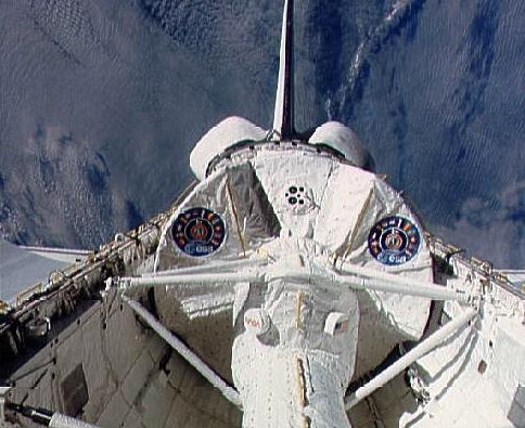
View of the Spacelab module in the payload bay of the Columbia during STS-9
Credit: NASA
AKA: Neurolab;USML. Status: Operational 1983. First Launch: 1983-11-28. Last Launch: 1998-04-17. Number: 16 . Height: 7.00 m (22.90 ft).
The Spacelab was designed by the European Space Agency to fit in the US space shuttle payload bay and allow extended experiments to be conducted by astronauts in orbit. Spacelab and the Canadian remote manipulator arm were the remnants of NASA's efforts to internationalize the shuttle program at its inception. In the absence of an American space station, Spacelab provided the only opportunity for America to carry out extensive man-tended experiments in space from the first Spacelab flight in 1983 until the Shuttle-Mir program in 1995.
Spacelab's modules could be varied to meet specific mission requirements. Its four principal components were the pressurized module, which contained a laboratory with a shirt-sleeve working environment; one or more open pallets that exposed materials and equipment to space; a tunnel to gain access to the module from the shuttle cabin; and an instrument pointing subsystem. Spacelab was not deployed free of the orbiter, although ESA did consider free-flying configurations at various times over the years.
On Sept. 24, 1973, a memorandum of understanding was signed between the European Space Agency, formerly known as the European Space Research Organization, and NASA with NASA's George C. Marshall Space Flight Center as lead center for ESA to design and develop Spacelab. An industrial consortium headed by ERNO-VFW Fokker (Zentralgesellschoft VFW-Fokker mbh) was named by ESA in June 1974 to build the pressurized modules. Five 10-foot-long, unpressurized, U-shaped pallet segments were built by the British Aerospace Corporation under contract to ERNO-VFW Fokker. The IPS was built by Dornier.
The pressurized module, or laboratory, was available in two segments. One, called the core segment, contained supporting systems, such as data processing equipment and utilities for the pressurized modules and pallets (if pallets were used in conjunction with the pressurized modules). The laboratory had fixtures, such as floor-mounted racks and a workbench. The second, called the experiment segment, provided more working laboratory space and contained only floor-mounted racks. When only one segment was needed, the core segment was used. Each pressurized segment was a cylinder 4.12 m in outside diameter and 2.74 m long. When both segments were assembled with end cones, their maximum outside length was 7.0 m.
The pressurized segment or segments were structurally attached to the orbiter payload bay by four attach fittings consisting of three longeron fitting sets (two primary and one stabilizing) and one keel fitting. The segment or segments were covered with passive thermal control insulation.
The ceiling skin panel of each segment contained a 1.3 m-diameter opening for mounting a viewport adapter assembly, a Spacelab window adapter assembly or scientific airlock; if none of these items were used, the openings were closed with cover plates that were bolted in place. The module shell was made from 2219-T851 aluminum plate panels. Eight rolled integral-machined waffle patterns were butt-welded together to form the shell of each module segment. The shell thickness ranges from 1.5 to 3.6 cm.
Because of the orbiter's center-of-gravity conditions, the Spacelab pressurized module or modules could not be installed at the forward end of the payload bay. Therefore, a pressurized tunnel was provided for equipment and crew transfer between the orbiter's pressurized crew compartment and the Spacelab pressurized module or modules. The transfer tunnel was a cylindrical structure with an internal unobstructed diameter of one meter. The cylinder was assembled in sections to allow length adjustment for different module configurations. Two tunnel lengths could be used-a long tunnel of 5.76 m and a short tunnel of 2.66 m. The joggle section of the tunnel compensates for the 1.07 m vertical offset of the orbiter middeck to the Spacelab pressurized module's centerline. There were flexible sections on each end of the tunnel near the orbiter and Spacelab interfaces. The tunnel was built by McDonnell Douglas Astronautics Company, Huntington Beach, Calif.
The airlock in the middeck of the orbiter, the tunnel adapter, hatches, the tunnel extension and the tunnel itself permitted the flight crew members to transfer from the orbiter middeck to the Spacelab pressurized module or modules in a pressurized shirt-sleeve environment. The airlock, tunnel adapter, tunnel and Spacelab pressurized module or modules were at ambient pressure before launch. In addition, the middeck airlock, tunnel adapter and hatches permit crew members outfitted for extravehicular activity to transfer from the airlock/tunnel adapter in space suits to the payload bay without depressurizing the orbiter crew compartment and Spacelab module or modules. If an EVA was required, no flight crew members were permitted in the Spacelab tunnel or module.
Some research to be accomplished on Spacelab missions requires that instruments be pointed with very high accuracy and stability at stars, the sun, the Earth or other targets of observation. The Instrument Pointing Subsystem (IPS) provided precision pointing for a wide range of payloads, including large single instruments or a cluster of instruments or a single small-rocket-class instrument. The pointing mechanism could accommodate instruments of diverse sizes and weights (up to 7 metric tons) and could point them to within 2 arc seconds and hold them on target to within 1.2 arc seconds.
Each pallet was more than a platform for mounting instrumentation; with an igloo attached, it could also cool equipment, provide electrical power and furnish connections for commanding and acquiring data from experiments. When only pallets were used, the Spacelab pallet portions of essential systems required for supporting experiments (power, experiment control, data handling, communications, etc.) were protected in a pressurized, temperature-controlled igloo housing.
The pallets were designed for large instruments, experiments requiring direct exposure to space or systems needing unobstructed or broad fields of view, such as telescopes, antennas and sensors (e.g., radiometers and radars). The U-shaped pallets were covered with aluminum honeycomb panels. A series of hard points attached to the main pallet structure was provided for mounting heavy payload equipment. Up to five segments could be flown on a single mission. Each pallet train was held in place in the payload bay by a set of five attach fittings, four longeron sill fittings and one keel fitting. Pallet-to-pallet joints were used to connect the pallets to form a single rigid structure called a pallet train. Twelve joints were used to connect two pallets.
The Spacelab electrical power distribution subsystem controlled and distributed main, essential and emergency dc and ac power to Spacelab subsystems and experiment equipment. Orbiter fuel cell power plants 2 and 3 provided dc power to orbiter main buses B and C, respectively. The orbiter electrical power distribution system was capable of distributing 7 kilowatts maximum continuous (12 kilowatts peak) power to Spacelab subsystems and experiments during on-orbit phases. If a single fuel cell failed on orbit, the system remained operational with a maximum power level of 5 kilowatts continuous and 8 kilowatts peak. The primary dc power received in the Spacelab from the orbiter primary payload bus was nominally 28 volts, a maximum of 32 volts and a worst-case minimum of 23 volts.
The Spacelab command and data management system provided a variety of services to Spacelab experiments and subsystems. Most of the CDMS commands were carried out through the use of the computerized system aboard Spacelab, called the data processing assembly. The DPA formatted telemetry data and transferred the information to the orbiter for transmission, received command data from the orbiter and distributed them to Spacelab subsystems, transferred data from the orbiter to experiments, and distributed timing signals from the orbiter to experiments.
The CDMS included three identical computers and assorted peripherals. One computer was dedicated to Spacelab experiments, one supported Spacelab subsystems, and the third was a backup. The flight crew monitored and operated Spacelab subsystems and payload experiments through data display and keyboard units. The three identical MATRA 125/MS computers had a main memory capacity of 64K 16-bit words. These three computers were later changed to the upgraded AP-101SL orbiter computers.
The Spacelab pressurized module video system interfaced with the orbiter closed-circuit television system and the orbiter Ku-band signal processor. The orbiter CCTV system accepted three video inputs from the Spacelab system.
The Spacelab intercom master station interfaced with the orbiter audio central control unit and the orbiter EVA/ATC transceiver for communications through orbiter duplex (simultaneous talk and listen) audio channels.
The Spacelab environmental control subsystem consisted of the atmosphere storage and control subsystem and the atmosphere revitalization system. The atmosphere storage and control subsystem received gaseous oxygen from the orbiter power reactant storage and distribution system and gaseous nitrogen from a tank located on the Spacelab module's exterior. The Spacelab ASCS regulated the gaseous oxygen and nitrogen pressure and flow rates to provide a shirt-sleeve environment for the Spacelab module compatible with the orbiter cabin atmosphere.
Gaseous oxygen from the orbiter PRSD entered the Spacelab module through the upper feed-through in the Spacelab forward end cone at 7 bar and a maximum flow rate of 6 kg per hour. The Spacelab cabin depressurization assembly was primarily for contingency dump of Spacelab cabin atmosphere in case of fire that could not be handled by the Spacelab fire suppression system, The module would be depressurized at 0.2 kg per second. The Spacelab active thermal control subsystem consisted of a water loop to remove heat from the Spacelab module and a Freon loop to remove heat from equipment on any pallets that were flown with the pressurized module.
| STS-40 Spacelab SLS-1. Carried life sciences experiments. |
| STS-42 Spacelab International Microgravity Laboratory-1. |
| STS-47 Spacelab-J. First on-time Shuttle launch since November 1985. First Japanese astronaut aboard shuttle. First African-American woman to fly in space. First married couple to fly on the same space mission. Conducted microgravity and biology experiments. |
| STS-50 Spacelab USML-1 (United States Microgravity Laboratory). First extended-duration shuttle mission. |
| STS-51-B Spacelab 3. Deployed Nusat. Conducted materials processing, environmental, life science, astrophysics, and technology experiments. Suffered the worst O-ring erosion experienced prior to the loss of Challenger |
| STS-51-F Spacelab 2. At 5 minutes, 45 seconds into ascent the number one engine shut down prematurely due to a sensor problem and an abort to orbit was declared. Despite the anomaly the mission continued. Launched PDP; carried Spacelab 2. |
| STS-51-K Planned Spacelab-D1 shuttle mission. Cancelled after Challenger disaster. No crew selected; renamed STS-61A |
| STS-55 Spacelab-D2. German materials experiments. |
| STS-58 Spacelab SLS-2. Biological, microgravity experiments. |
| STS-59 Spacelab SRL-1 / SIR-C SAR radar. The Space Radar Laboratory obtained radar high-resolution images of approximately 25 percent of the planet's land surfaces. |
| STS-61-A Spacelab D-1. Record set of eight crew launched aboard a single spacecraft. First Dutch astronaut. Launched GLOMR. Six of the eight crew members were divided into a blue and red team working 12-hour shifts. Experienced O-ring erosion. |
| STS-65 First Japanese woman to fly in space. Carried IML-2; microgravity, biology experiments. |
| STS-71-E Planned SLS-1 shuttle mission. Cancelled after Challenger disaster. |
| STS-73 Carried USML-2 for microgravity experiments. |
| STS-78 Life and Microgravity Spacelab; human biological and microgravity experiments. |
| STS-81-G Planned Spacelab-J shuttle mission. Cancelled after Challenger disaster. |
| STS-81-M Planned SLS-2 shuttle mission. Cancelled after Challenger disaster. |
| STS-83 First Microgravity Science Laboratory (MSL-1) mission. Orbiter recalled to earth after three days of flight when one of three fuel cells failed. Mission reflown as STS-94. |
| STS-9 Spacelab 1. First West German to fly in space. First Spacelab mission. Record six crew size in a single spacecraft. Suspect exhaust nozzle on right solid rocket booster. Landing delayed when two computers failed. Landed on fire when hydraulic pump leaked. |
| STS-90 Neurolab. |
| STS-94 First shuttle mission reflight (same vehicle, crew, and payload as curtailed STS-83 mission). MSL-1 Microgravity Science Laboratory. |
Family: Space station module, USA - Space Stations. Country: USA. Spacecraft: Spacelab, Mir. Flights: STS-71-A, STS-71-M, STS-81-G, STS-51-K. Launch Vehicles: Space Shuttle. Launch Sites: Cape Canaveral, Cape Canaveral LC39A, Cape Canaveral LC39B. Agency: NASA, NASA Houston, Bremen, Alenia. Bibliography: 2, 276, 279, 3152, 3157, 3176, 3180, 3181, 3185, 3186, 4, 6.
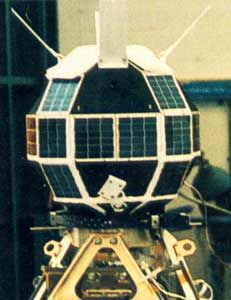 | GLOMR Credit: Manufacturer Image |
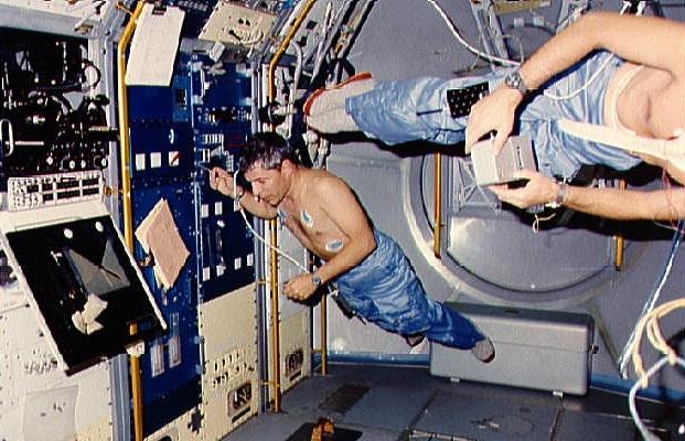 | STS-9 STS-9 crewmembers Parker and Merbold floating about the Spacelab module Credit: NASA |
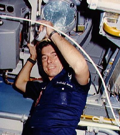
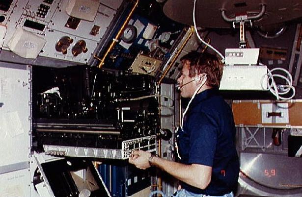 | STS-9 Payload Specialist Byron K. Lichtenberg working in the Spacelab Credit: NASA |
 | STS-9 View of payload bay as seen from Spacelab aft viewing area Credit: NASA |
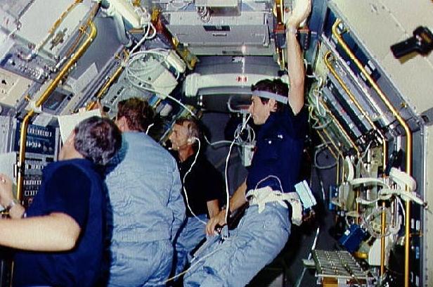 | STS-9 STS-9 crewmembers gather around television monitor in Spacelab module Credit: NASA |
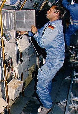
 | STS-9 Payload Specialist Ulf Merbold working in the Spacelab Credit: NASA |
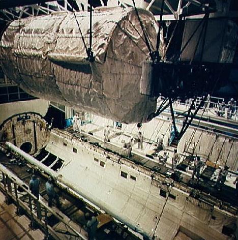 | STS-51-B Spacelab D-1 being installed in the Challenger payload bay Credit: NASA |
 | STS-51-B Artist concept of Spacelab in orbiter cargo bay with horizon Credit: NASA |
 | STS-61-A STS 61-A crewmembers in Spacelab D-1 science module Credit: NASA |
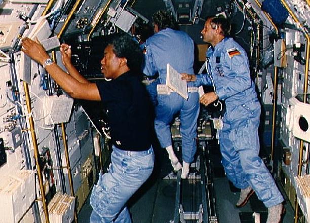 | STS-61-A STS 61-A crewmembers in Spacelab D-1 science module Credit: NASA |
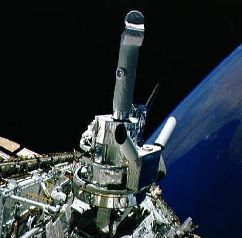 | STS-51-F View of Spacelab 2 pallet in the open payload bay Credit: NASA |
1983 November 28 - . 16:00 GMT - . Launch Site: Cape Canaveral. Launch Complex: Cape Canaveral LC39A. Launch Platform: MLP1. LV Family: Shuttle. Launch Vehicle: Space Shuttle.
- Spacelab 1 - . Payload: SL 1 LM. Nation: USA. Agency: NASA. Program: Spacelab. Class: Manned. Type: Manned space laboratory. Spacecraft: Spacelab. Decay Date: 1983-12-08 . USAF Sat Cat: 14523 . COSPAR: 1983-116xx. Apogee: 239 km (148 mi). Perigee: 231 km (143 mi). Inclination: 57.00 deg. Period: 89.20 min.
- Spacelab 1 Pallet - . Payload: SL 1 PLT. Nation: USA. Agency: NASA. Program: Spacelab. Class: Manned. Type: Manned space laboratory. Spacecraft Bus: Shuttle Attached Payloads. Spacecraft: SLP. Decay Date: 1983-12-08 . USAF Sat Cat: 14523 . COSPAR: 1983-116xx. Apogee: 239 km (148 mi). Perigee: 231 km (143 mi). Inclination: 57.00 deg. Period: 89.20 min.
1983 December 8 - .
- Landing of STS-9 - . Return Crew: Garriott, Lichtenberg, Merbold, Parker, Shaw, Young. Nation: USA. Related Persons: Garriott, Lichtenberg, Merbold, Parker, Shaw, Young. Program: Spacelab. Flight: STS-9. STS-9 landed at 23:47 GMT. .
1985 April 29 - . 16:02 GMT - . Launch Site: Cape Canaveral. Launch Complex: Cape Canaveral LC39A. Launch Platform: MLP2. LV Family: Shuttle. Launch Vehicle: Space Shuttle.
- Spacelab 3 - . Payload: SL 3 LM. Nation: USA. Agency: NASA. Program: Spacelab. Class: Manned. Type: Manned space laboratory. Spacecraft: Spacelab. Decay Date: 1985-05-06 . USAF Sat Cat: 15665 . COSPAR: 1985-034xx. Apogee: 359 km (223 mi). Perigee: 346 km (214 mi). Inclination: 57.00 deg. Period: 91.60 min.
1985 May 6 - .
- Landing of STS-51-B - . Return Crew: Gregory, Lind, Overmyer, Thagard, Thornton, Bill, van den Berg, Lodewijk, Wang. Nation: USA. Related Persons: Gregory, Lind, Overmyer, Thagard, Thornton, Bill, van den Berg, Lodewijk, Wang. Program: Spacelab. Flight: STS-51-B. STS-51-B landed at 16:13 GMT. .
1985 July 29 - . 21:00 GMT - . Launch Site: Cape Canaveral. Launch Complex: Cape Canaveral LC39A. Launch Platform: MLP2. LV Family: Shuttle. Launch Vehicle: Space Shuttle.
- Spacelab 2 PLT - . Nation: USA. Agency: NASA. Program: Spacelab. Class: Manned. Type: Manned space laboratory. Spacecraft Bus: Shuttle Attached Payloads. Spacecraft: SLP. Decay Date: 1985-08-06 . USAF Sat Cat: 15925 . COSPAR: 1985-063xx. Apogee: 328 km (203 mi). Perigee: 300 km (180 mi). Inclination: 49.50 deg. Period: 90.80 min.
- Spacelab 2 PLT - . Nation: USA. Agency: NASA. Program: Spacelab. Class: Manned. Type: Manned space laboratory. Spacecraft Bus: Shuttle Attached Payloads. Spacecraft: SLP. Decay Date: 1985-08-06 . USAF Sat Cat: 15925 . COSPAR: 1985-063xx. Apogee: 328 km (203 mi). Perigee: 300 km (180 mi). Inclination: 49.50 deg. Period: 90.80 min.
- Spacelab 2 PLT - . Nation: USA. Agency: NASA. Program: Spacelab. Class: Manned. Type: Manned space laboratory. Spacecraft Bus: Shuttle Attached Payloads. Spacecraft: SLP. Decay Date: 1985-08-06 . USAF Sat Cat: 15925 . COSPAR: 1985-063xx. Apogee: 328 km (203 mi). Perigee: 300 km (180 mi). Inclination: 49.50 deg. Period: 90.80 min.
1985 August 6 - .
- Landing of STS-51-F - . Return Crew: Acton, Bartoe, Bridges, England, Fullerton, Henize, Musgrave. Nation: USA. Related Persons: Acton, Bartoe, Bridges, England, Fullerton, Henize, Musgrave. Program: Spacelab. Flight: STS-51-F. STS-51-F landed at 19:52 GMT. .
1985 October 30 - . 17:00 GMT - . Launch Site: Cape Canaveral. Launch Complex: Cape Canaveral LC39A. Launch Platform: MLP1. LV Family: Shuttle. Launch Vehicle: Space Shuttle.
- Spacelab D-1 - . Payload: Spacelab Long Module. Nation: USA. Agency: NASA. Program: Spacelab. Class: Manned. Type: Manned space laboratory. Spacecraft: Spacelab. Decay Date: 1985-11-06 . USAF Sat Cat: 16230 . COSPAR: 1985-104xx. Apogee: 332 km (206 mi). Perigee: 322 km (200 mi). Inclination: 57.00 deg. Period: 91.10 min.
1985 November 6 - .
- Landing of STS-61-A - . Return Crew: Bluford, Buchli, Dunbar, Furrer, Hartsfield, Messerschmid, Nagel, Ockels. Nation: USA. Related Persons: Bluford, Buchli, Dunbar, Furrer, Hartsfield, Messerschmid, Nagel, Ockels. Program: Spacelab. Flight: STS-61-A. STS-61-A landed at 18:01 GMT. .
1990 December 11 - .
- Landing of STS-35 - . Return Crew: Brand, Durrance, Gardner, Guy, Hoffman, Lounge, Parise, Parker. Nation: USA. Related Persons: Brand, Durrance, Gardner, Guy, Hoffman, Lounge, Parise, Parker. Program: Spacelab. Flight: STS-35. STS-35 landed at 05:48 GMT. .
1991 June 5 - . 13:24 GMT - . Launch Site: Cape Canaveral. Launch Complex: Cape Canaveral LC39B. Launch Platform: MLP3. LV Family: Shuttle. Launch Vehicle: Space Shuttle.
- Spacelab SLS 1 - . Payload: Spacelab Long Module. Nation: USA. Agency: NASA. Program: Spacelab. Class: Manned. Type: Manned space laboratory. Spacecraft: Spacelab. Decay Date: 1991-06-14 . USAF Sat Cat: 21399 . COSPAR: 1991-040xx. Apogee: 289 km (179 mi). Perigee: 276 km (171 mi). Inclination: 39.00 deg. Period: 90.20 min.
1991 June 14 - .
- Landing of STS-40 - . Return Crew: Bagian, Gaffney, Gutierrez, Hughes-Fulford, Jernigan, O Connor, Seddon. Nation: USA. Related Persons: Bagian, Gaffney, Gutierrez, Hughes-Fulford, Jernigan, O Connor, Seddon. Program: Spacelab. Flight: STS-40. STS-40 landed at 15:40 GMT. .
1992 January 22 - . 14:52 GMT - . Launch Site: Cape Canaveral. Launch Complex: Cape Canaveral LC39A. Launch Platform: MLP3. LV Family: Shuttle. Launch Vehicle: Space Shuttle.
- Spacelab IML-1 - . Payload: Spacelab Long Module. Nation: USA. Agency: NASA. Program: Spacelab. Class: Manned. Type: Manned space laboratory. Spacecraft: Spacelab. Decay Date: 1992-01-30 . USAF Sat Cat: 21846 . COSPAR: 1992-002xx. Apogee: 299 km (185 mi). Perigee: 286 km (177 mi). Inclination: 57.00 deg. Period: 90.40 min.
1992 January 30 - .
- Landing of STS-42 - . Return Crew: Bondar, Grabe, Hilmers, Merbold, Oswald, Readdy, Thagard. Nation: USA. Related Persons: Bondar, Grabe, Hilmers, Merbold, Oswald, Readdy, Thagard. Program: Spacelab. Flight: STS-42. STS-42 landed at 16:07 GMT. .
1992 April 2 - .
- Landing of STS-45 - . Return Crew: Bolden, Duffy, Foale, Frimout, Leestma, Lichtenberg, Sullivan. Nation: USA. Related Persons: Bolden, Duffy, Foale, Frimout, Leestma, Lichtenberg, Sullivan. Program: Spacelab. Flight: STS-45. STS-45 landed at 11:21 GMT. .
1992 June 25 - . 16:12 GMT - . Launch Site: Cape Canaveral. Launch Complex: Cape Canaveral LC39A. Launch Platform: MLP3. LV Family: Shuttle. Launch Vehicle: Space Shuttle.
- USML-1 - . Payload: Spacelab Long Module. Nation: USA. Agency: NASA. Program: Spacelab. Class: Manned. Type: Manned space laboratory. Spacecraft: Spacelab. Decay Date: 1992-07-09 . USAF Sat Cat: 22000 . COSPAR: 1992-034xx. Apogee: 301 km (187 mi). Perigee: 245 km (152 mi). Inclination: 28.50 deg. Period: 90.00 min.
1992 July 9 - .
- Landing of STS-50 - . Return Crew: Baker, Bowersox, DeLucas, Dunbar, Meade, Richards, Trinh. Nation: USA. Related Persons: Baker, Bowersox, DeLucas, Dunbar, Meade, Richards, Trinh. Program: Spacelab. Flight: STS-50. STS-50 landed at 11:51 GMT. .
1992 September 12 - . 14:23 GMT - . Launch Site: Cape Canaveral. Launch Complex: Cape Canaveral LC39B. Launch Platform: MLP2. LV Family: Shuttle. Launch Vehicle: Space Shuttle.
- Spacelab J LM - . Payload: Spacelab Long Module. Nation: USA. Agency: NASA. Program: Spacelab. Class: Manned. Type: Manned space laboratory. Spacecraft: Spacelab. Decay Date: 1992-09-20 . USAF Sat Cat: 22120 . COSPAR: 1992-061xx. Apogee: 308 km (191 mi). Perigee: 297 km (184 mi). Inclination: 57.00 deg. Period: 90.60 min.
1992 September 20 - .
- Landing of STS-47 - . Return Crew: Apt, Brown, Davis, Gibson, Jemison, Lee, Mohri. Nation: USA. Related Persons: Apt, Brown, Davis, Gibson, Jemison, Lee, Mohri. Program: Spacelab. Flight: STS-47. STS-47 landed at 12:55 GMT. .
1993 April 17 - .
- Landing of STS-56 - . Return Crew: Cameron, Cockrell, Foale, Ochoa, Oswald. Nation: USA. Related Persons: Cameron, Cockrell, Foale, Ochoa, Oswald. Program: Spacelab. Flight: STS-56. STS-56 landed at 11:40 GMT. .
1993 April 26 - . 14:50 GMT - . Launch Site: Cape Canaveral. Launch Complex: Cape Canaveral LC39A. Launch Platform: MLP3. LV Family: Shuttle. Launch Vehicle: Space Shuttle.
- Spacelab D-2 LM - . Payload: Spacelab Long Module. Nation: USA. Agency: NASA. Program: Spacelab. Class: Manned. Type: Manned space laboratory. Spacecraft: Spacelab. COSPAR: 1993-027xx.
1993 May 5 - .
- Landing of STS-55 - . Return Crew: Harris, Henricks, Nagel, Precourt, Ross, Schlegel, Walter. Nation: USA. Related Persons: Harris, Henricks, Nagel, Precourt, Ross, Schlegel, Walter. Program: Spacelab. Flight: STS-55. STS-55 landed at 14:29 GMT. .
1993 October 18 - . 14:53 GMT - . Launch Site: Cape Canaveral. Launch Complex: Cape Canaveral LC39B. Launch Platform: MLP1. LV Family: Shuttle. Launch Vehicle: Space Shuttle.
- Spacelab SLS 2 LM - . Payload: Spacelab Long Module. Nation: USA. Agency: NASA. Program: Spacelab. Class: Manned. Type: Manned space laboratory. Spacecraft: Spacelab. Decay Date: 1993-11-01 . USAF Sat Cat: 22869 . COSPAR: 1993-065xx. Apogee: 277 km (172 mi). Perigee: 259 km (160 mi). Inclination: 39.00 deg. Period: 89.90 min.
1993 November 1 - .
- Landing of STS-58 - . Return Crew: Blaha, Fettman, Lucid, McArthur, Searfoss, Seddon, Wolf. Nation: USA. Related Persons: Blaha, Fettman, Lucid, McArthur, Searfoss, Seddon, Wolf. Program: Spacelab. Flight: STS-58. STS-58 landed at 15:05 GMT. .
1994 July 8 - . 16:43 GMT - . Launch Site: Cape Canaveral. Launch Complex: Cape Canaveral LC39A. Launch Platform: MLP3. LV Family: Shuttle. Launch Vehicle: Space Shuttle.
- Spacelab IML 2 - . Payload: Spacelab Long Module. Nation: USA. Agency: NASA. Program: Spacelab. Class: Manned. Type: Manned space laboratory. Spacecraft: Spacelab. Decay Date: 1994-07-23 . USAF Sat Cat: 23173 . COSPAR: 1994-039xx. Apogee: 249 km (154 mi). Perigee: 239 km (148 mi). Inclination: 28.50 deg. Period: 89.40 min.
1994 July 23 - .
- Landing of STS-65 - . Return Crew: Cabana, Chiao, Halsell, Hieb, Mukai, Thomas, Walz. Nation: USA. Related Persons: Cabana, Chiao, Halsell, Hieb, Mukai, Thomas, Walz. Program: Spacelab. Flight: STS-65. STS-65 landed at 10:39 GMT. .
1994 November 14 - .
- Landing of STS-66 - . Return Crew: Brown, Clervoy, McMonagle, Ochoa, Parazynski, Tanner. Nation: USA. Related Persons: Brown, Clervoy, McMonagle, Ochoa, Parazynski, Tanner. Program: Spacelab. Flight: STS-66. STS-66 landed at 15:34 GMT. .
1995 March 18 - .
- Landing of STS-67 - . Return Crew: Durrance, Gregory, William, Grunsfeld, Jernigan, Lawrence, Oswald, Parise. Nation: USA. Related Persons: Durrance, Gregory, William, Grunsfeld, Jernigan, Lawrence, Oswald, Parise. Program: Spacelab. Flight: STS-67. STS-67 landed at 21:48 GMT. .
1995 June 27 - . 19:32 GMT - . Launch Site: Cape Canaveral. Launch Complex: Cape Canaveral LC39A. Launch Platform: MLP3. LV Family: Shuttle. Launch Vehicle: Space Shuttle.
- Spacelab-Mir LM - . Payload: Spacelab Long Module. Nation: USA. Agency: NASA. Program: Mir. Class: Manned. Type: Manned space laboratory. Flight: Soyuz TM-21, STS-71, STS-71 Mir EO-19. Spacecraft: Spacelab. Decay Date: 1995-07-06 . USAF Sat Cat: 23600 . COSPAR: 1995-030xx. Apogee: 396 km (246 mi). Perigee: 48 km (29 mi). Inclination: 51.60 deg. Period: 88.90 min.
1995 October 20 - . 13:53 GMT - . Launch Site: Cape Canaveral. Launch Complex: Cape Canaveral LC39B. Launch Platform: MLP3. LV Family: Shuttle. Launch Vehicle: Space Shuttle.
- Spacelab USML-2 - . Payload: Spacelab Long Module. Nation: USA. Agency: NASA. Program: Spacelab. Class: Manned. Type: Manned space laboratory. Spacecraft: Spacelab. Decay Date: 1995-11-05 . USAF Sat Cat: 23688 . COSPAR: 1995-056xx. Apogee: 267 km (165 mi). Perigee: 256 km (159 mi). Inclination: 39.00 deg. Period: 89.70 min.
1995 November 5 - .
- Landing of STS-73 - . Return Crew: Bowersox, Coleman, Catherine, Leslie, Lopez-Alegria, Rominger, Sacco, Thornton. Nation: USA. Related Persons: Bowersox, Coleman, Catherine, Leslie, Lopez-Alegria, Rominger, Sacco, Thornton. Program: Spacelab. Flight: STS-73. STS-73 landed at 11:46 GMT. .
1996 June 20 - . 14:49 GMT - . Launch Site: Cape Canaveral. Launch Complex: Cape Canaveral LC39B. Launch Platform: MLP3. LV Family: Shuttle. Launch Vehicle: Space Shuttle.
- Spacelab LMS 1 - . Payload: Spacelab Long Module. Nation: USA. Agency: NASA Houston. Program: Spacelab. Class: Manned. Type: Manned space laboratory. Spacecraft: Spacelab. Decay Date: 1996-07-07 . USAF Sat Cat: 23931 . COSPAR: 1996-036xx. Apogee: 261 km (162 mi). Perigee: 246 km (152 mi). Inclination: 39.00 deg. Period: 89.60 min.
1996 July 7 - .
- Landing of STS-78 - . Return Crew: Brady, Favier, Helms, Henricks, Kregel, Linnehan, Thirsk. Nation: USA. Related Persons: Brady, Favier, Helms, Henricks, Kregel, Linnehan, Thirsk. Program: Spacelab. Flight: STS-78. STS-78 landed at 12:36 GMT. .
1997 April 4 - . 19:20 GMT - . Launch Site: Cape Canaveral. Launch Complex: Cape Canaveral LC39A. Launch Platform: MLP3. LV Family: Shuttle. Launch Vehicle: Space Shuttle.
- MSL-1 Spacelab - . Payload: Spacelab Long Module 1. Nation: USA. Agency: NASA Houston. Manufacturer: Bremen. Program: Spacelab. Class: Manned. Type: Manned space laboratory. Spacecraft: Spacelab. Decay Date: 1997-04-08 . USAF Sat Cat: 24755 . COSPAR: 1997-013xx. Apogee: 302 km (187 mi). Perigee: 298 km (185 mi). Inclination: 28.50 deg. Period: 90.50 min. Remained attached to OV-102.
1997 April 8 - .
- Landing of STS-83 - . Return Crew: Crouch, Gernhardt, Halsell, Kilrain, Linteris, Thomas, Voss, Janice. Nation: USA. Related Persons: Crouch, Gernhardt, Halsell, Kilrain, Linteris, Thomas, Voss, Janice. Program: Spacelab. Flight: STS-83. STS-83 landed at 18:33 GMT. .
1997 July 1 - . 18:02 GMT - . Launch Site: Cape Canaveral. Launch Complex: Cape Canaveral LC39A. Launch Platform: MLP1. LV Family: Shuttle. Launch Vehicle: Space Shuttle.
- Spacelab MSL-1R - . Payload: Spacelab Long Module. Nation: USA. Agency: NASA Houston. Manufacturer: Bremen. Program: Spacelab. Class: Manned. Type: Manned space laboratory. Spacecraft: Spacelab. Decay Date: 1997-07-17 . USAF Sat Cat: 24849 . COSPAR: 1997-032xx. Apogee: 300 km (180 mi). Perigee: 296 km (183 mi). Inclination: 28.50 deg. Period: 90.50 min. Remained attached to OV-102.
1998 April 17 - . 18:19 GMT - . Launch Site: Cape Canaveral. Launch Complex: Cape Canaveral LC39B. Launch Platform: MLP2. LV Family: Shuttle. Launch Vehicle: Space Shuttle.
- Neurolab - . Payload: Spacelab. Nation: USA. Agency: NASA. Program: Spacelab. Class: Manned. Type: Manned space laboratory. Spacecraft: Spacelab. Decay Date: 1998-05-03 . USAF Sat Cat: 25297 . COSPAR: 1998-022xx. Apogee: 274 km (170 mi). Perigee: 247 km (153 mi). Inclination: 39.00 deg. Period: 89.70 min.
1998 May 3 - .
- Landing of STS-90 - . Return Crew: Altman, Buckey, Hire, Linnehan, Pawelczyk, Searfoss, Williams, Dave. Nation: USA. Related Persons: Altman, Buckey, Hire, Linnehan, Pawelczyk, Searfoss, Williams, Dave. Program: Spacelab. Flight: STS-90. STS-90 landed at 16:09 GMT. .
Back to top of page
Home - Search - Browse - Alphabetic Index: 0- 1- 2- 3- 4- 5- 6- 7- 8- 9
A- B- C- D- E- F- G- H- I- J- K- L- M- N- O- P- Q- R- S- T- U- V- W- X- Y- Z
© 1997-2019 Mark Wade - Contact
© / Conditions for Use