
Home - Search - Browse - Alphabetic Index: 0- 1- 2- 3- 4- 5- 6- 7- 8- 9
A- B- C- D- E- F- G- H- I- J- K- L- M- N- O- P- Q- R- S- T- U- V- W- X- Y- Z
ODERACS
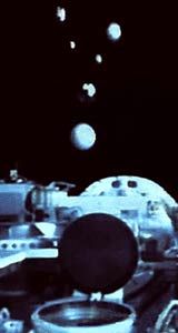 ODERACS Credit: Manufacturer Image |
AKA: CGP;HH. Status: Operational 1992. First Launch: 1992-12-02. Last Launch: 1995-02-03. Number: 20 . Gross mass: 4,200 kg (9,200 lb).
The primary objective was to calibrate the Haystack Long Range Imaging Radar (LRIR) and validate the JSC Orbital Debris Analysis System (ODAS). These measurements and resulting data processing were a complete success.
The Haystack radar was used for orbital debris measurements in an unorthodox way. Instead of moving the radar dish to track satellites, the dish "stares" in a fixed direction. Debris objects that fly through the radar beam produce echoes that are recorded on magnetic tape. Analysis of the echo data must take into account that debris objects can fly through the radar beam from any direction and can cross the beam at any position. Entirely new analysis tools had to be developed to deal with this novel kind of data. Because of the complexity of this process, we felt that an end-to-end calibration of the radar and the associated data processing system was essential in order to be confident that the debris data derived from the radar were valid.
The question relating to radar operation was: Is the radar calibrated correctly, such that the measured radar cross section was the correct one? The question relating to the data processing system was: Are the physical sizes and orbital parameters calculated from the Haystack radar data correct? The only way to do these calibrations was to place known objects into orbit and measure them with the Haystack radar. From a practical point of view, metal spheres were the best choice for test objects, since their radar cross section was independent of aspect angle, and their shape makes them easy to deploy from the Shuttle Orbiter bay.
A problem with spheres was that they return only one polarization of radar waves (the Principal Polarization of PP). For this reason, the Haystack radar could be calibrated only for PP returns using spheres. Since irregular debris objects return both PP and OP (Orthogonal Polarization) signals, it was necessary to make an independent calibration of the radar for its response to OP returns. Wire dipole targets were used for this purpose, since they reflect exactly equal OP and PP polarizations.
The first mission, ODERACS 1, calibrated the PP response of the Haystack radar and the data processing system by launching calibrated metal spheres. The second mission, ODERACS 2 calibrated the OP response relative to the PP response by launching small wire dipoles. Spheres were also launched on the second mission to provide additional tests of the radar calibration and data processing system, and to provide orbital markers to help ground-based radars locate and track the tiny dipoles.
The ODERACS 1 flight experiment, flown on Discovery STS-60 in February 1994, deployed six spheres: two 6-inch diameter, two 4-inch diameter, and two 2-inch diameter. The spheres remained in orbit from eight to thirteen months and completely burned up upon re-entry. ODERACS 2 which was flown on Discovery STS-63 in February 1995, deployed three spheres (2-inch, 4-inch, and 6-inch diameters) and three dipoles (two 5.255 x .040 inch dipoles, and one 1.740 x .040 inch dipole). The ODERACS 2 targets remained in orbit from seventeen days to thirteen months.
The Haystack radar collected multiple measurements from the different ODERACS targets. The data were recorded from tracking, fly-through, and spiral scanning passes. The calibration accuracy was determined from the tracking passes by comparing the measured radar cross section (RCS) with the theoretical. Tables A and B below show the results from these tracking passes. The small difference between the spheres measured and theoretical RCS values verifies the calibration accuracy of the Haystack radar for PP returns. The measurements from the dipoles showed that the primary polarization (PP) and orthogonal (OP) return signals were very closely balanced, which was the primary objective of ODERACS 2. The larger differences between the dipoles measured and theoretical RCS indicates that the dipoles were tumbling in a plane that was skewed some 15 to 35 degrees from the radar.
The fly-through data, along with the spiral scanning data (which was used to determine the Haystack radar beam shape) was used to validate the ODAS software. After initial processing, some anomalies in the ODAS software were discovered and subsequently corrected. Initially, the spread in the RCS data from the theoretical was 4.5 dB; after the software modifications, the spread was reduced to 1.0 dB. This represents an improvement of 35 percent.
The optical effort associated with ODERACS was largely an "effort-of-opportunity" that was secondary to the purpose of calibrating the Haystack radar, but nonetheless, was shown to be useful for verification of orbital debris optical observational techniques and data analysis. A wide variety of optical sensors were able to view the 4-inch and 6-inch spheres and determine them to have magnitudes very similar to their predicted values. For example, a diameter of 3.93 +/- 0.24 inches was derived from the analysis of a CCD image of the ODERACS 1 4-inch diffuse sphere obtained from the NASA-JSC CCD Debris Telescope at Maui. In this case, the geometry and albedo of the object were well known, so this excellent result verified the optical data analysis process leading to debris piece sizes.
More at: ODERACS.
Family: Military, Military target sat, Surveillance. Country: USA. Launch Vehicles: Space Shuttle. Launch Sites: Cape Canaveral, Cape Canaveral LC39A, Cape Canaveral LC39B. Bibliography: 2, 276, 6.
1992 December 2 - . 13:24 GMT - . Launch Site: Cape Canaveral. Launch Complex: Cape Canaveral LC39A. Launch Platform: MLP1. LV Family: Shuttle. Launch Vehicle: Space Shuttle.
- ODERACS F - . Nation: USA. Agency: NASA. Program: STS. Spacecraft: ODERACS. Decay Date: 1992-12-09 . USAF Sat Cat: 22259 . COSPAR: 1992-086xx. Apogee: 321 km (199 mi). Perigee: 317 km (196 mi). Inclination: 57.00 deg. Period: 90.90 min.
- ODERACS E - . Nation: USA. Agency: NASA. Program: STS. Spacecraft: ODERACS. Decay Date: 1992-12-09 . USAF Sat Cat: 22259 . COSPAR: 1992-086xx. Apogee: 321 km (199 mi). Perigee: 317 km (196 mi). Inclination: 57.00 deg. Period: 90.90 min.
- ODERACS D - . Nation: USA. Agency: NASA. Program: STS. Spacecraft: ODERACS. Decay Date: 1992-12-09 . USAF Sat Cat: 22259 . COSPAR: 1992-086xx. Apogee: 321 km (199 mi). Perigee: 317 km (196 mi). Inclination: 57.00 deg. Period: 90.90 min.
- ODERACS C - . Nation: USA. Agency: NASA. Program: STS. Spacecraft: ODERACS. Decay Date: 1992-12-09 . USAF Sat Cat: 22259 . COSPAR: 1992-086xx. Apogee: 321 km (199 mi). Perigee: 317 km (196 mi). Inclination: 57.00 deg. Period: 90.90 min.
- ODERACS B - . Nation: USA. Agency: NASA. Program: STS. Spacecraft: ODERACS. Decay Date: 1992-12-09 . USAF Sat Cat: 22259 . COSPAR: 1992-086xx. Apogee: 321 km (199 mi). Perigee: 317 km (196 mi). Inclination: 57.00 deg. Period: 90.90 min.
- ODERACS A - . Nation: USA. Agency: NASA. Program: STS. Spacecraft: ODERACS. Decay Date: 1992-12-09 . USAF Sat Cat: 22259 . COSPAR: 1992-086xx. Apogee: 321 km (199 mi). Perigee: 317 km (196 mi). Inclination: 57.00 deg. Period: 90.90 min.
1994 February 3 - . 12:10 GMT - . Launch Site: Cape Canaveral. Launch Complex: Cape Canaveral LC39A. Launch Platform: MLP3. LV Family: Shuttle. Launch Vehicle: Space Shuttle.
- ODERACS E - . Payload: Discovery F18 / WSF 1 / BremSat 1 / ODERACS A, .... Mass: 5.00 kg (11.00 lb). Nation: USA. Agency: NASA Houston. Class: Surveillance. Type: Radar calibration target. Spacecraft: ODERACS. Decay Date: 1995-03-03 . USAF Sat Cat: 22994 . COSPAR: 1994-006F. Apogee: 356 km (221 mi). Perigee: 337 km (209 mi). Inclination: 57.00 deg. Period: 91.50 min. Orbital Debris Radar Calibration Sphere; deployed from STS-60. Space craft engaged in investigation of spaceflight techniques and technology (US Cat A). .
- ODERACS F - . Payload: Discovery F18 / WSF 1 / BremSat 1 / ODERACS A, .... Mass: 5.00 kg (11.00 lb). Nation: USA. Agency: NASA Houston. Class: Surveillance. Type: Radar calibration target. Spacecraft: ODERACS. Decay Date: 1995-02-24 . USAF Sat Cat: 22995 . COSPAR: 1994-006G. Apogee: 356 km (221 mi). Perigee: 338 km (210 mi). Inclination: 57.00 deg. Period: 91.50 min. Orbital Debris Radar Calibration Sphere; deployed from STS-60. Space craft engaged in investigation of spaceflight techniques and technology (US Cat A). .
- ODERACS A - . Payload: Discovery F18 / WSF 1 / BremSat 1 / ODERACS A, .... Mass: 4.00 kg (8.80 lb). Nation: USA. Agency: NASA Houston. Class: Surveillance. Type: Radar calibration target. Spacecraft: ODERACS. Decay Date: 1994-10-02 . USAF Sat Cat: 22990 . COSPAR: 1994-006B. Apogee: 352 km (218 mi). Perigee: 327 km (203 mi). Inclination: 57.00 deg. Period: 91.30 min. Orbital Debris Radar Calibration Sphere; deployed from STS-60. Space craft engaged in investigation of spaceflight techniques and technology (US Cat A). .
- ODERACS B - . Payload: Discovery F18 / WSF 1 / BremSat 1 / ODERACS A, .... Mass: 4.00 kg (8.80 lb). Nation: USA. Agency: NASA Houston. Class: Surveillance. Type: Radar calibration target. Spacecraft: ODERACS. Decay Date: 1994-10-04 . USAF Sat Cat: 22991 . COSPAR: 1994-006C. Apogee: 352 km (218 mi). Perigee: 332 km (206 mi). Inclination: 57.00 deg. Period: 91.40 min. Orbital Debris Radar Calibration Sphere; deployed from STS-60. Space craft engaged in investigation of spaceflight techniques and technology (US Cat A). .
- ODERACS D - . Payload: Discovery F18 / WSF 1 / BremSat 1 / ODERACS A, .... Mass: 1.00 kg (2.20 lb). Nation: USA. Agency: NASA Houston. Class: Surveillance. Type: Radar calibration target. Spacecraft: ODERACS. Decay Date: 1994-12-31 . USAF Sat Cat: 22993 . COSPAR: 1994-006E. Apogee: 353 km (219 mi). Perigee: 329 km (204 mi). Inclination: 56.90 deg. Period: 91.35 min. Orbital Debris Radar Calibration Sphere; deployed from STS-60. .
- ODERACS C - . Payload: Discovery F18 / WSF 1 / BremSat 1 / ODERACS A, .... Mass: 1.00 kg (2.20 lb). Nation: USA. Agency: NASA Houston. Class: Surveillance. Type: Radar calibration target. Spacecraft: ODERACS. Decay Date: 1994-12-31 . USAF Sat Cat: 22992 . COSPAR: 1994-006D. Apogee: 353 km (219 mi). Perigee: 329 km (204 mi). Inclination: 56.90 deg. Period: 91.35 min. Orbital Debris Radar Calibration Sphere; deployed from STS-60. .
1995 February 3 - . Launch Site: Cape Canaveral. Launch Complex: Cape Canaveral LC39B. Launch Platform: MLP2. LV Family: Shuttle. Launch Vehicle: Space Shuttle.
- ODERACS IIF - . Nation: USA. Agency: NASA. Class: Surveillance. Type: Radar calibration target. Spacecraft: ODERACS. Decay Date: 1996-11-26 . USAF Sat Cat: 23476 . COSPAR: 1995-004H. Apogee: 258 km (160 mi). Perigee: 250 km (150 mi). Inclination: 98.30 deg. Period: 89.60 min. Reentered? .
- ODERACS 2A - . Mass: 5.00 kg (11.00 lb). Nation: USA. Agency: NASA Houston. Class: Surveillance. Type: Radar calibration target. Spacecraft: ODERACS. Decay Date: 1996-03-13 . USAF Sat Cat: 23471 . COSPAR: 1995-004C. Apogee: 280 km (170 mi). Perigee: 268 km (166 mi). Inclination: 51.60 deg. Period: 87.10 min. Orbital Debris Radar Calibration spheres; deployed from STS 63 2/4/95..
- ODERACS 2B - . Mass: 4.00 kg (8.80 lb). Nation: USA. Agency: NASA Houston. Class: Surveillance. Type: Radar calibration target. Spacecraft: ODERACS. Decay Date: 1995-09-29 . USAF Sat Cat: 23472 . COSPAR: 1995-004D. Apogee: 179 km (111 mi). Perigee: 177 km (109 mi). Inclination: 51.60 deg. Period: 88.10 min. Orbital Debris Radar Calibration spheres; deployed from STS 63 2/4/95. Reentered Sep 29 .
- ODERACS 2C - . Mass: 1.00 kg (2.20 lb). Nation: USA. Agency: NASA Houston. Class: Surveillance. Type: Radar calibration target. Spacecraft: ODERACS. Decay Date: 1996-02-07 . USAF Sat Cat: 23473 . COSPAR: 1995-004E. Orbital Debris Radar Calibration spheres; deployed from STS 63 2/4/95. Reentered? .
- CGP/ODERACS - . Payload: HH-M. Nation: USA. Agency: NASA. Program: Mir. Spacecraft: ODERACS. Decay Date: 1995-02-11 . USAF Sat Cat: 23469 . COSPAR: 1995-004xx. Apogee: 390 km (240 mi). Perigee: 386 km (239 mi). Inclination: 51.60 deg. Period: 92.30 min.
- ODERACS 2D - . Mass: 1.00 kg (2.20 lb). Nation: USA. Agency: NASA Houston. Class: Surveillance. Type: Radar calibration target. Spacecraft: ODERACS. Decay Date: 1995-03-02 . USAF Sat Cat: 23474 . COSPAR: 1995-004F. Apogee: 265 km (164 mi). Perigee: 246 km (152 mi). Inclination: 51.60 deg. Period: 89.60 min. Orbital Debris Radar Calibration spheres; deployed from STS 63 2/4/95. Reentered Mar 2 .
- ODERACS 2E - . Mass: 1.00 kg (2.20 lb). Nation: USA. Agency: NASA Houston. Class: Surveillance. Type: Radar calibration target. Spacecraft: ODERACS. Decay Date: 1995-02-27 . USAF Sat Cat: 23475 . COSPAR: 1995-004G. Apogee: 270 km (160 mi). Perigee: 261 km (162 mi). Inclination: 51.60 deg. Period: 89.80 min. Orbital Debris Radar Calibration spheres; deployed from STS 63 2/4/95. Reentered Feb 27 .
Back to top of page
Home - Search - Browse - Alphabetic Index: 0- 1- 2- 3- 4- 5- 6- 7- 8- 9
A- B- C- D- E- F- G- H- I- J- K- L- M- N- O- P- Q- R- S- T- U- V- W- X- Y- Z
© 1997-2019 Mark Wade - Contact
© / Conditions for Use