
Home - Search - Browse - Alphabetic Index: 0- 1- 2- 3- 4- 5- 6- 7- 8- 9
A- B- C- D- E- F- G- H- I- J- K- L- M- N- O- P- Q- R- S- T- U- V- W- X- Y- Z
Lunex
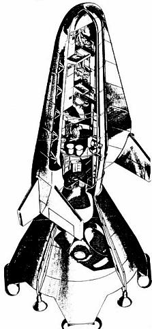 Lunex Lunar Lander USAF Lunex lunar lander. The Lunex lifting body re-entry vehicle, for three crew, is mounted atop the Lunar Launching Stage, which in turn is nested in the Lunar Landing Stage. |
Status: Study 1958.
In May 1961, just as Kennedy had decided that NASA should put an American on the moon, the US Air Force released a secret report, summarizing the result of years of planning to place a military base on the moon by 1967. Lunex was not a race against the Russians, but rather a plan to achieve the 'strategic high ground'. It is interesting to note the following:
- If Project Lunex had been pursued instead of Apollo, the United States would have ended the sixties with a launch vehicle very similar to the Shuttle - solid rocket boosters, a Lox-LH2 core, a lifting re-entry vehicle. This clearly could have provided a better basis for follow-on programs than Apollo did. The USAF launch vehicle studies of the late 1960's again came up with a very similar configuration, and NASA finally came to the same conclusion for the Shuttle design as well. One advantage of the Lunex booster is that it also provided a heavy-lift launch vehicle in the pure cargo version.
- The report reveals the reason for USAF support of development of the advanced and large rocket engines begun in the late 1950's: the LR-115 (RL-10), J-2, F-1, M-1, and large solid rocket motors. The RL-10, designed for the USAF from the beginning as a throttleable motor for the Lunex lunar lander, finally put this capability to use twenty years later in the DC-X VTOL vehicle.
- The schedule was extremely over-optimistic. First lunar landing was by the end of 1966, while the booster and vehicle were considerably more advanced than the Apollo approach. Examples include:
- Lox-LH2 in the lunar landing stages, including throttleability and months-long lunar hibernation times between engine restarts
- Mach 35 lifting body re-entry vehicle
- Computer data storage capabilities and technologies not even achieved today
- Electrostatic gyro platforms (not perfected until the late 1970's in the B-52's SPN-GNS platform)
- Many of the techniques for Project Lunex reappear in Korolev's early L3 lunar expedition plans. These include the selection of base sites by automated probes; the planting of homing transponders on the lunar surface for precision landing of manned landers and cargo craft (by Surveyor spacecraft in Lunex, by Luna Ye-8 landers and Lunokhods in the Russian plans); and methods of direct lunar landing.
- The Intelligence Section contains a mixture of erroneous beliefs as to the characteristics of the booster stages of the R-7 launch vehicle, mixed with some accurate intelligence on the upper stages (calculable from tracking and telemetry intercepts for Turkey). It would seem that as of this date no accurate intelligence or photograph of the R-7 vehicle on the pad had been made. The information as to Soviet intentions (no plans to go to the moon) was more accurate. It would seem that both the USAF and Kennedy picked the moon goal as one in which the Russians were not really interested.
LUNAR EXPEDITION PLAN - LUNEX
<
LUNEX
HEADQUARTERS
SPACE SYSTEMS DIVISION
AIR FORCE SYSTEMS COMMAND
DOWNGRADED AT 12 YEAR
This document provides a plan for a manned Lunar Expedition. It was prepared to furnish more detailed information in support of the National Space Program proposed by a USAF committee chaired by Major General J R Holzapple. That report pointed out the dire need for a goal for our national apace program. The Lunar Expedition was chosen as the goal since it not only provides a sufficient challenge to the nation, but also provides technical fall-outs for greatly improved apace capabilities.
Previous editions of this plan have provided guidance and incentive to Air Force technical groups. Consequently, their efforts have established a broad technical base within the Air Force from which rapid advances can be made. This capability has been taken into account in laying out the accelerated schedules in this plan.
O J RITLAND
This document contains information affecting the national defense of the United States within the meaning of the Espionage Laws, Title 18, U S.C. Section 793 and 794, the transmission or revelation of which in any manner to an unauthorized person is prohibited by law
I. SUMMARY
II. PROGRAM DESCRIPTION
III. MASTER SCHEDULES
IV. DEVELOPMENT- TEST - PRODUCTION
V. BUDGET AND FINANCIAL
VI. PROGRAM MANAGEMENT
VII. MATERIEL SUPPORT
VIII. CIVIL ENGINEERING
IX. PERSONNEL AND TRAINING
X. INTELLIGENCE
Appendix #1 Glossary of Terms
FOR
LUNAR EXPEDITION
Approved by
Norair M. Lulejian
WDLAR-S-458
SECRET
LUNAR EXPEDITION
PLAN
Lunex Lunar Lander
USAF Lunex lunar lander. The Lunex lifting body re-entry vehicle, for three crew, is mounted atop the Lunar Launching Stage, which in turn is nested in the Lunar Landing Stage.
MAY 1961
INTERVALS. NOT AUTOMATICALLY
DECLASSIFIED. DOD DIR 5200.10
WDLAR-S-458
SECRET
AIR FORCE SYSTEMS COMMAND
Major General, USAF
Commander
CONTENTS
Colonel, USAF
Director, Advanced
Systems Plans and Analysis
SECTION I - SUMMARY
1.1 PURPOSE
The Lunar Expedition has as its objective manned exploration of the moon with the first manned landing and return in late 1967. This one achievement if accomplished before the USSR, will serve to demonstrate conclusively that this nation possesses the capability to win future competition in technology. No space achievement short of this goal will have equal technological significance, historical impact, or excite the entire world.
1.2 BACKGROUND
Extensive studies by Air Force-Industry teams during 1958, 1959, and 1960 examined all facets of the problem and techniques of sending men to the moon and resulted in a feasible concept which is attainable at an early date and is economical and reliable. Laboratories within the Air Force participated in this effort, thus establishing a broad technological base which can react quickly to an expanded high priority program.
1.3 DESCRIPTION
The lunar mission would be initiated by the launching of the lunar payload by a large, three-stage liquid or solid propellant booster to escape velocity on a lunar intercept trajectory. The payload, consisting of a Lunar Landing Stage, Lunar Launching Stage and a manned vehicle, would use a lunar horizon scanner and a Doppler altimeter for orientation prior to a soft landing using the Lunar Landing Stage. Terminal guidance using pre-positioned beacons would be required for landing at a pre-selected site. The Lunar Launch Stage would provide the necessary boost for the return to earth of the manned Lunex Re-entry Vehicle. Using mid-course guidance and aerodynamic braking, the vehicle would effect re-entry and a normal unpowered aircraft landing at a ZI base.
In addition to the manned vehicle a cargo payload is included in this plan. The cargo payload would utilise the same three-stage earth launch booster and the same lunar landing techniques. However it would not be returned to earth and would be used only to transport supplies and cargo to the expedition on the moon.
The primary concept recommended in this plan is the "direct shot" method since studies have indicated it could be available at an earlier date and it would be more reliable. Another concept is also suggested which consists of the rendezvous and assembly of components in an earth orbit before ejection into a lunar trajectory. The techniques and development required for this latter concept are documented under a separate SSP titled, SAINT. Therefore, no details of this concept are presented in this plan. All schedules relating the two plans have been co-ordinated to insure compatibility and to take advantage of mutual advances. Since neither rendezvous techniques nor large boosters have been demonstrated, both approaches must be pursued until it becomes obvious that one of them has clear advantages over the other.
The following developments are required in order to accomplish the lunar expedition:
a. A three-man Lunex Re-entry Vehicle. This vehicle must be capable of re-entry into the earth's atmosphere at velocities of 37, 000 ft/sec. It must also be capable of making a conventional aircraft landing. Control and improved guidance for entering the earth's atmosphere at the proper place and angle is needed as well as improved materials to withstand the high surface temperatures. Adequate life support equipment is also required. The development of this vehicle is the key to the accomplishment of the Lunex program and is one of the pacing development items. A detailed schedule for its development is included.
b A Lunar Landing Stage for decelerating and landing the entire payload. This stage must have the capability to decelerate 134,000 pounds from a velocity of almost 9,000 ft/sec to 20 ft/sec at touchdown. A Doppler altimeter is required to provide information for ignition and control of the engine. Horizon scanners must be used to orient the payload to the local vertical.
c. A Lunar Launch Stage capable of launching the manned Lunex Re-entry Vehicle from the lunar surface. Lunar ascent guidance is required to place the vehicle on the proper trajectory.
d. A three-stage earth launch booster, referenced as a space launching system. The first stage will use either LOX/LH2 with six million pounds of thrust or a solid fuel with an equivalent launch capability. The second and third stages will use LOX/LH2. The development of this space launching system is considered the pacing development item for the Lunex program. Because of the magnitude of the booster program and the applicability of the booster to other programs, the plan for its development is being presented separately.
In addition to the above listed hardware developments, additional information is required about the lunar surface such as its physical and roughness characteristics. High resolution photographs of the entire lunar surface may provide this information. Present NASA plans if expedited could provide the information for this Lunex program. NASA's Surveyor (soft lunar landing) program could also incorporate radio-light beacons which would be used later in conjunction with a terminal landing system. A core sample of lunar material is required as soon as possible so that design of lunar landing devices and lunar facilities can be accomplished.
1.4 MAJOR PROBLEM AREAS
The development of techniques for re-entering the earth's atmosphere at 37,000 ft/sec is one of the major problems. Guidance equipment must be very accurate to insure that the re-entry angle is within +- 2°. Too steep an entry angle will cause overheating and intolerable G loads, while too shallow an entry angle may permit the Lunex Re-entry Vehicle to skip out of the atmosphere into a highly eccentric earth orbit. If this happens, the vehicle may spend several days in the trapped radiation belts and may exceed the time limits of the ecological system.
The Lunar Landing Stage will be a difficult development because of a requirement for orientation with the local vertical when approaching the moon. It must also be guided to the selected landing site. Many tests will be required to develop the necessary equipment.
The Lunar Launching Stage will be another difficult development. The pre-launch countdown must be performed automatically and, if the launching booster is not vertical upon launch, corrections must be made in order to attain the required moon-earth trajectory.
Although the foregoing developments are difficult, no technological break-through will be required. All designs can be based on extrapolation of present technology.
1.5 MILESTONES
Major milestones in the program are:
a. Recovery of a manned re-entry vehicle from 50,000 miles in 1965.
b. Manned Circumlunar flight in 1966.
c. Manned lunar landing and return in 1967.
These and other significant events are shown on Chart I-A.
1.6 CAPABILITIES DEVELOPED
The development of large boosters, rendezvous techniques and manoeuvrable space vehicles, all required for the Lunar Expedition, will also provide a capability for many new and advanced space achievements. For example, the Space Launching System which will boost 134,000 pounds to escape velocity will boost approximately 350,000 pounds into a 300 nm orbit, or will launch a manned vehicle on a pass around either Mars or Venus.
1.7 MANAGEMENT ACTIONS REQUIRED
The major Management Milestones for FY62 and FY63 are shown on Chart I-B. Immediate attention by Management to obtain Program Approval and Funding by July 1961 is necessary if the United States is to put a "man on the moon" by August 1967.
Throughout the Lunex program time allocated for management and Air Force technical evaluations has been kept to a minimum. This is essential to meet the schedules, and delays in providing funding as indicated, or in receiving notification of required decisions, will have the direct effect of delaying the program end objective.
SECTION II - PROGRAM DESCRIPTION
2.0 BACKGROUND
Shortly after the first Sputnik was launched in October 1957, Headquarters, ARDC initiated a series of studies to examine the military potential of space operations. These studies were accomplished by Industry-Air Force teams each working independently. Two of these studies which were the forerunners of this Lunex plan were "Lunar Observatory" and "Strategic Lunar System." The objective of the first study was to examine an economical, sound and logical approach for establishing a manned intelligence observatory on the moon, and the second study examined the military potential of lunar operations. These studies showed that it is technically and economically feasible to build a manned lunar facility.
A third study titled, "Permanent Satellite Base and Logistic Study" is presently under way and will be completed in August 1961. This study will provide a conceptual design of a three-man re-entry vehicle which will carry men to and from the moon. The three-man vehicle is the key item in the lunar transportation system as its weight will dictate the booster sizes. For this reason it is given special attention in this plan.
2.1 Lunex PROGRAM OBJECTIVE
The objective of the Lunar Expedition program is the manned exploration of the moon with the first manned lunar landing to occur as soon as possible. The execution of this plan will land three men on the moon and return them during the 3rd quarter of calendar year 1967, and will establish the Lunar Expedition in 1968. Completion of this plan will require the development of equipment, materials, and techniques to transport men to and from the lunar surface and to provide a lunar facility which will allow men to live and work in the extremely harsh lunar environment.
2.2 Lunex PROGRAM - DESCRIPTION
The Lunar Expedition Program is primarily concerned with the development of the equipment necessary to transport men and supplies to the lunar surface.
The key development in this program is the Lunar Transport Vehicle which is composed of the Space Launching System and either the Manned Lunar Payload or the Cargo Payload. The Manned Lunar Payload consists of a three-man Lunex Re-Entry Vehicle, a Lunar Launch Stage, and a Lunar Landing Stage. The same Lunar Landing Stage, plus a cargo package, composes the Cargo Payload. The relative effort required for the development of these two payloads in comparison with other portions of the complete Lunar Expedition Program is shown in Figure 2-1. A breakdown of the Lunar Transport Vehicle is shove in Figure 2-2.
The Space Launching System consists of a three-stage booster capable of placing either the Manned Lunar Payload or the Cargo Payload on a lunar intercept trajectory at escape velocity. This plan does not contain development information on the Launching System since such information is contained in a separate System Package Plan being prepared concurrently. The development schedules in these plans have been co-ordinated to insure compatibility.
In operation, the Manned Lunar Payload, weighing 134,000 pounds, will be boosted to escape velocity of approximately 37,000 ft/sec on a trajectory which intercepts the moon. Velocity will be sufficient to reach the moon in approximately 2 1/2 days. As the Manned Lunar Payload approaches the moon it is oriented with the local vertical by the use of horizon scanners. The Lunar Landing Stage decelerates the Manned Lunar Payload for a soft landing at a pre-selected site using an altitude sensing device to determine time of ignition. Landing at the pre-selected site will be accomplished using terminal guidance equipment and a prepositioned beacon to effect an offset landing.
The Lunar Launching Stage, using the Landing Stage as a base, will launch the Lunex Re-entry Vehicle on the return trajectory. In early test shots before men are included, the countdown and launch will be effected automatically by command from the earth. Small mid-course corrections may be necessary to insure re-entry into the earth's atmosphere within allowable corridor limits.
The Lunex Re-entry Vehicle will re-enter the earth's atmosphere within the allowable corridor so that it will not skip back into space again nor burn from excess heat. It will use aerodynamic braking to decelerate and will have sufficient lift capability to effect a normal unpowered aircraft landing at a base such as Edwards Air Force Base.
Several successful unmanned completely automatic flights of the type just described must be completed in order to establish confidence in the system reliability before manned missions will be attempted.
Cargo will be transported to the lunar surface using the same procedures and equipment except that the Lunar Launch Stage is not needed. The Cargo Package will have a weight equal to the combined weight of the Lunex Re-entry Vehicle and the Lunar Launch Stage.
As a separate approach to the problem of placing large payloads on the moon, techniques of rendezvous and assembly in earth orbit are being examined. Use of these techniques would require the launch, rendezvous and orbital assembly of sections of the Manned Lunar Payload and the Cargo Payload along with the required orbital launch booster and its fuel. The assembled vehicle would then be boosted from orbital velocity to escape velocity and would proceed as described above. Details of the major developments required such as rendezvous, docking and orbital assembly are outlined in a System Package Plan titled SAINT, being prepared concurrently. All programming information and schedules have been co-ordinated with this plan to insure compatibility and mutual support.
2.3 DESIGN PHILOSOPHY
The Lunar Expedition Plan has been oriented toward the development of a useful capability rather than the accomplishment of a difficult task on a one-time basis. The use of a large booster is favoured for the direct shot approach since studies have shown this to be more reliable, safer and more economical as well as having earlier availability. However, another approach using a smaller booster in conjunction with orbital rendezvous and assembly is also considered.
The manned Lunex Re-entry Vehicle is the key item in determining booster sizes. Its weight determines the size of the Lunar Launch Stage which in turn determined the size of the Lunar Landing Stage. The total weight of these three items is the amount that must be boosted to earth escape velocity by the Space Launching System. In this manner the size of the Space Launching System was determined.
A 2 1/2 day trajectory each way was selected as a conservative design objective. Longer flights would have more life support and guidance problems while shorter flights require higher boost velocity.
An abort capability will be included in the design insofar as possible. The next section describes the abort system in considerable detail.
Development and tests are scheduled on a high priority basis. Thus, the schedules shown in this plan are dictated by technological limitations and not by funds.
The entire program as described herein is an integrated program in that later development tests build on the results of early tests. Thus, equipment and techniques are proved out early, and confidence in the reliability is obtained by the time a man is included.
2.4 ABORT PHILOSOPHY
The insertion of a man into a space system creates a safety and reliability problem appreciably greater than the problem faced by any unmanned system. It is well recognised that maximum reliability is desirable, but also known that reliabilities in excess of 85 to 90% are extremely difficult to achieve with systems as complex as the Lunar Transportation System. Therefore, the need for an abort system to protect the man during the "unreliable" portions of the lunar mission is accepted.
A review of the proposed techniques and equipment to provide "full abort" capability has shown that due to payload limitations this is not practical during the early lunar missions. Thus a reasonable element of risk will be involved. In order to decrease this element of risk and to understand where it occurs the lunar mission has been divided into six time periods. These time periods are as follows:
a. Earth ascent.
b. Earth-moon transit.
c. Lunar terminal.
d. Lunar ascent.
e. Moon-earth transit.
f. Re-entry.
The development and test philosophy for this program is to launch the manned systems as early as possible in the program, but in an unmanned status. This will provide experience and allow the system to be checked out and "man-rated" before the first manned flight. It also means that the Lunex Re-entry Vehicle will be used for orbital and circumlunar flights prior to the lunar landing and return flight. The propulsion systems used for these early flights will be used throughout the program and the experience gained from each flight will increase the probability of success in reaching the final lunar landing and return objective. Also these propulsion systems will be used concurrently in other programs and at the time of man-rating will possess greater launch experience than can be expected for the largest booster of the Space Launching System. This would indicate that a larger number of unmanned flights should be scheduled for the larger full boost system than for the early nights. It also points out the need for a sophisticated Earth Ascent Abort capability during the first manned lunar landing and return flight.
In providing an abort philosophy for the Lunar Program it should be noted that the Lunar Re-entry Vehicle, the Lunar Landing Stage and the Lunar Launching Stage all possess inherent abort capability if utilised properly during an emergency. With sufficient velocity the re-entry vehicle is capable of appreciable manoeuvring and landing control to provide its own recovery system. The Lunar Launching and Lunar Landing Stages possess an appreciable delta-v capability that can be used to alter the payload trajectory to better accomplish recovery of the man. However, in either case the manoeuvres mill have to rely on computing techniques to select the best possible abort solution for any specific situation.
With this background, and with the understanding that in a future final design effort "full abort" may be required, the following abort design objectives for the Manned Lunar Payload are presented:
- Earth Ascent Phase
- On Pad - Full abort system will be provided.
- Lift-off to Flight Velocity for the Re-entry Vehicle - Full abort system will be provided.
- Flight Velocity for the Re-entry Vehicle to Escape Velocity - The basic Manned Lunar Payload will provide the abort capability.
- On Pad - Full abort system will be provided.
- Earth-Moon Transit
- Injection - Abort capability to compensate for injection error is desired as part of the basic Manned Lunar Payload. Computing, propulsion, etc., capabilities should be designed into the basic system to provide for the selection of the optimum abort trajectory.
- Mid-Course - Abort capability during Earth-Moon transit is desired for the Re-Entry Vehicle by means of a direct earth return, earth orbit, or circumlunar flight and earth return. Circumlunar flight generally requires the least, but the actual selection of the optimum trajectory should be accomplished when required by a computing capability, and executed by the Lunar Payload.
- Injection - Abort capability to compensate for injection error is desired as part of the basic Manned Lunar Payload. Computing, propulsion, etc., capabilities should be designed into the basic system to provide for the selection of the optimum abort trajectory.
- Lunar Terminal
This type of abort generally results from loss of propulsion or control of the Lunar Landing Stage. Where possible the Lunar Launching Stage will be used to attain a direct or circumlunar trajectory that terminates in an earth return. When this is not possible the Lunar Launching Stage will be used to accomplish the safest possible lunar landing. Recovery of the crew will not be provided in this system and selection of the above alternatives will be accomplished automatically on-board. Crew recovery will be provided by another stand-by Lunar Transport Vehicle.
- Lunar Ascent
Maximum inherent reliability by over-design of components and systems in the Lunar Launching Stage seems to be the most logical approach for this phase due to the extreme weight penalty imposed by a separate abort system.
The early missions will be faced with the highest risk, but as a facility on the lunar surface is developed, a rescue capability and the addition of an abort capability can be developed. No specific abort system will be provided for this phase, but consideration should be given to the possibility of future lunar modifications to provide for abort.
- Moon-Earth Transit
This would generally be associated with a gross trajectory error, or loss of control on re-entry. The only solution is to utilise the on-board capability that remains to achieve an earth orbit. After achieving orbit an earth-launched rescue mission would be initiated. This approach requires no additional abort system to be provided for this phase.
- Re-entry
Exceeding re-entry corridor limits, or loss of control could cause an emergency where abort would be desirable. Should sufficient delta-V remain from the over-design of the lunar launch stage, and not be used during Moon-Earth transit this would be used to attain an earth orbit where rescue could be achieved. No separate abort capability is required for this phase, but availability of propellant should be considered.
A detailed plan must be prepared for the complete Lunar Expedition operation. This plan must start from the first time man lands on the lunar surface and account for every single effort, or objective he is to accomplish during his stay on the surface. A crew of three men will be sent into a new and hostile environment where rescue or assistance from other human beings will be extremely difficult, if not impossible, for the first mission. Time will be at a premium and all items of equipment must be planned, designed and delivered in the Cargo Payloads so that they can be used in the easiest possible manner.
The procedures for first exploring the surface and then for constructing the expedition facility must all be derived, demonstrated and proven by earth operations prior to attempting the desired operation on the moon. An environmental facility that simulates the lunar surface with sufficient work area to test out equipment and procedures will be required.
 Lunex Chart I - A Lunar Expedition Program Milestone Schedule |
The best photographic resolution to date is around one-half mile on the lunar surface, which provides adequate data for charts having a scale of 1:1,350,000. Good astronomical telescopes can be used to improve on the photographic data and obtain sufficient detail to prepare sectional charts like the one included. However, larger scale, accurate lunar charts will be required to complete detailed plans. Data can be obtained for such charts from a lunar orbiting photographic satellite which will provide sufficient resolution and overlap to enable stereographic compilation of contours and elevations. The NASA proposed Lunar Orbiter program is a possible source of the required data.
Planning for construction of the expedition facility can begin only after detailed surface information becomes available. Examination of returned lunar core samples will be necessary before plans can be completed.
SECTION III
MASTER SCHEDULES
3.0 INTRODUCTION
The establishment of the Lunar Expedition Program as a national objective will provide a worthy goal for the United States industrial and governmental organizations. The Lunar Expedition program has been based on extensive study, design, and research work during the past three years.
A Lunar Expedition program will require the use and centralised control of a major portion of the present military space capability. This will have the effect of giving the military program a scheduled long-range objective, and still provide useable military capabilities throughout the period. As an example, manned re-entry vehicles for orbital operations will be available in early 1965. They will be followed by a manned lunar re-entry vehicle in 1966.
Propulsion and Space Launching systems will be required to support the Lunex program. The program will set orbital and escape velocity payload requirements ranging from 20 to 350 thousand pounds in a 300 mile orbit and from 24,000 to 134,000 pounds at escape velocity. This capability will be obtained at an accelerated pace for the Lunex program and as a result the same capability will be available for military use much earlier than could be achieved if the start of the development programs had to be justified at this time entirely on the basis of military usefulness.
The accomplishment of the Lunex program will require maximum use of several presently programmed efforts and reorientation of others. The major program of direct interest to the Lunex are the SAINT and BOSS programs. Therefore, these efforts have been co-ordinated and integrated with the Lunex program. The BOSS shots will provide the necessary orbital primate test data to allow the manned life support package for the Lunex Re-entry Vehicle to be designed. The SAINT unmanned and manned program will provide additional orbital information on rendezvous, docking, and personnel and fuel transfer. In the event that the direct shot approach for the lunar expedition requires reorientation in future years to use orbital assembly techniques this capability will be available from the SAINT program.
3.1 MASTER PROGRAM PHASING CHART
This schedule presents the integrated military program required to accomplish the Liner Expedition mission and to develop techniques for operating in the earth orbital and lunar arena. It was prepared to indicate the interface between this Lunar Expedition System Package Plan and the Space Launching system. The major national objective of this integrated program is to land men on the moon and return them in August of 1967.
3.2 LUNAR EXPEDITION PROGRAM SCHEDULE
This schedule presents the major items to be accomplished as a result of the Lunex program. The costing as shown on the schedule does not include the cost of developing the Space Launching System since this is provided under a separate System Package Plan. However, the cost of purchasing the flight vehicles is included.
The major "prestige" milestones of the program can be summarised as follows:
- First Manned Orbital Flight (3 Man Space Vehicle) - April 1965
- First Lunar Landing Cargo) - July 1966
- Manned Circumlunar Flight - Sept. 1966
- Manned Lunar Landing & Return - Aug. 1967
- Permanently Manned Lunar Expedition Jan. 1968
This schedule indicates the major Lunex program efforts required during fiscal years 1962 and 1963. The time allocation for management and Air Force technical evaluations have been kept to a minimum in order to meet the end objective of "man on the moon" in August 1967.
Several critical major decisions are required and are summarised below:
- Program Approval & Funding - July 1961
- Development-Production Funding - Dec. 1962
- Design Concept Decision - Jan. 1963
- Approval for Hardware Go-Ahead - Feb. 1963
3.4 LUNAR EXPEDITION TEST SCHEDULE
This schedule presents the major test items required for the Lunex program. Upon completion of the program, manned transport and unmanned cargo vehicles will be available to support the Lunar Expedition. The cargo vehicle will be capable of transporting approximately 45,000 pound "cargo packages" to the lunar surface for supporting the expedition. This same vehicle would be capable of transporting future military payloads to the lunar surface to support space military operations.
A detailed high-speed re-entry test program and an abort system test program is scheduled to provide basic re-entry data and to insure the safety of the men in the Lunex Re-entry Vehicle.
Prior to the first "manned lunar landing and return" flight, a series of test and check-out flights will be required. These will initially consist of orbital flights, and then very high altitude (50,000 miles or more) elliptical flights for testing the vehicles under re-entry conditions. When these have been completed, the first flights will be made around the moon (circumlunar) and return to an earth base. With a completely man-rated vehicle, and unmanned lunar landing flights completed, man will then make the first landing on the moon for the purpose of selecting a site for the Lunar Expedition Facility.
3.5 LUNEX SPACE LAUNCHING REQUIREMENTS
The purpose of this schedule is to summarise the space launching vehicle requirements and indicate when the launches will be needed.
The THOR-ABLE-STAR boosters will be used for the re-entry test program. The Space Launching System boosters designated as A, AB and BC, and solids as required, will be needed as indicated and their payload capabilities are estimated as follows:
Booster: Payload
A 410: 20,000 pounds (300 mile orbit)
AB 825: 87,000 pounds (300 mile orbit)
AB 825: 24,000 pounds (escape velocity)
BC 2720: 134,000 pounds (escape velocity)
3.6 PERSONNEL AND TRAINING
The Lunar Expedition program will require military personnel and a military training program. Details of this program are presented in Section IX and summarised on the Lunex Training Schedule included in this section.
The number of personnel required will increase from a limited staff in the early Program Office to a total of 6,000 personnel in the active expedition year. This total does not include "in plant" contractor personnel which is estimated to be on the order of 60 thousand.
Training of military personnel to meet the requirements of the Lunex program will be done by contractor and military training personnel. Maximum use will be made of program equipment when it can be scheduled for training purposes and in addition, allocation of production equipment is necessary to meet training requirements.
3.7 LUNEX CIVIL ENGINEERING FACILITIES SCHEDULE
The facilities development and construction program is shown on this schedule. The first item to be accomplished is a site survey to determine the extent that the Lunex program can be supported by AMR and PMR. When this has been accomplished it will be possible to determine if the early Lunex test launches can be accomplished by using present facilities. Full consideration will be given to the possibility of building the Lunex Launch Complex as an expansion of the AMR or PMR. A more detailed presentation of the facilities program is contained in Section VIII, Civil Engineering.
DEVELOPMENT - TEST - PRODUCTION
4.0 INTRODUCTION
Implementation of the Lunar Expedition will require a completely integrated program involving the development, test, and production of items based on almost every known technical discipline. These technical disciplines are presently being investigated under a multitude of programs and organisations. The Lunar Expedition program will require these technical efforts to be immediately organised and re-oriented where necessary. This can best be accomplished by preparing a detailed development, test, and production program. When this program is completed each technical area can be evaluated by comparing its present program objectives and its required output to meet the Lunar Expedition program requirements. In the following paragraphs the Lunar Expedition development objectives and technical performance requirements are presented. The scope of the major existing technical programs and the necessary re-orientation is discussed.
4.1 DEVELOPMENT OBJECTIVES
4.1.1 HIGH SPEED RE-ENTRY
At the present time high-speed re-entry data in the velocity spectrum from 25,000 ft/sec to 45,000 ft/sec is non-existent. In order to meet the Lunex Re-entry Vehicle development schedule it will be necessary to have high-speed re-entry data during the engineering design program for the manned re-entry vehicle. Thus a compressed and co-ordinated test program for both ground test facilities and flight testing is necessary.
Immediate action is necessary to schedule and design the high-speed wind-tunnel test program. This will show the type of information that can only be achieved by means of flight testing.
The High-Speed Re-entry flight test program scheduled for the Lunex program is necessary to provide basic data on re-entry as well as to fly specific shapes in the later period of the test program. This selected shape program will be co-ordinated with the Lunex Re-entry Vehicle design effort.
In order to accomplish the High-Speed Re-entry flight test program it will be necessary to design and develop a test vehicle. This vehicle must use existing boost systems due to time limitations, but the payload will have to be designed especially for this program since none exists at this time. It is believed that the Atlas booster will prove adequate for these tests, but a decision must await the test payload design.
4.1.2 MANNED LUNAR PAYLOAD
The largest single development objective for the Lunex program is to provide a payload capable of transporting men and equipment to the lunar surface and returning them to a selected earth base. This payload would consist of a Lunar Landing Stage, Lunar Launch Stage and a 3-man Lunex Re-entry Vehicle.
A typical Manned Lunar Payload is shown in a cut-away view in Figure 4-1. The characteristics and General Arrangement of the Manned Lunar Payload are seen in Figures 4-2 and 4-3. This payload is 52 feet 11 inches long, has the c.g. located 33 feet 8 inches from the nose of the re-entry vehicle and the interface diameter with the Space Launching System is 25 feet. The complete payload weighs 134,000 pounds at escape velocity, and a 20,205 pound Manned Re-entry Vehicle is returned to the earth.
The Lunex Re-entry Vehicle must be capable of entering the earth's atmosphere with a velocity of approximately 37,000 ft/sec. At the present time, basic re-entry information for velocities of this magnitude does not exist. Therefore, engineering design effort for this re-entry vehicle must be accomplished concurrently with other major sub-systems developments and integrated with the High-Speed Re-entry test program and the Abort System test and development program. This requires close management control of these programs by the Lunex Program Office.
 Lunex Chart III-A Lunar Expedition Master Program Schedule |
The Lunar Landing Stage must be capable of landing the Lunar Launching Stage and the Lunex Re-entry Vehicle on the lunar surface. At the present time this is considered a difficult design problem because little is known about the lunar surface. Actually the best photographic resolution to date is approximately 1/2 mile. Many theories exist on the formation of the moon and therefore, the characteristics of its present surface. When these two factors are considered the only practical design approach is to provide an alighting system capable of landing on an extremely rough surface. An automatic levelling, orientation and launching system is required for system check-out prior to manned flight. Therefore, any assumption that the Manned Lunar Payload can be moved about on the lunar surface or that the payloads might initially transfer fuel on the lunar surface, might be entirely erroneous and jeopardise the complete Lunar Expedition effort. The landing stage will also have to be developed so that it is capable of landing the Cargo Payloads on the lunar surface.
The Lunar Launching Stage must be developed with a different philosophy than the previous sub-systems. First, it only operates in the vacuum of space and on the lunar surface. Secondly, it will be required to function after it has been located on the lunar surface for an extended period varying from several days to many months. Therefore, the stage must be developed to launch the re-entry vehicle after being subjected to a better vacuum then available in our best earth laboratory facilities, following possible temperature variations of 400 to 500 degrees, following possible meteorite bombardment and from a less than optimum launch angle. Specifically the stage development must consider propellant boil-off, automatic check-out, self-erection and remote (earth-moon) launching procedures.
The Lunar Launching Stage represents the major reliability problem of the system because an abort capability is planned for every phase of the Lunex mission except during launch from the lunar surface. During the early lunar flights an abort capability for this phase is just too expensive payload-wise for the Space Launching System. An abort capability during lunar launch essentially requires a duplicate lunar launching capability because the man must still be returned to the earth by either this system, or a special rescue flight. Therefore, until lunar support facilities are available, a separate system for abort during lunar launch does not seem practical. This creates the requirement to develop an extremely reliable Lunar Launching Stage.
4.1.3 CARGO PAYLOAD
The successful support of the Lunar Expedition will require a capability to deliver relatively large Cargo Packages to the lunar surface. These Cargo Packages will be soft landed at the desired lunar sites by the Lunar Landing Stage. Each Cargo Package will weigh approximately 45,000 pounds and will be specifically designed to carry the items desired to support the expedition. Development of the Cargo Payload and the specific packages will depend upon the Lunar Landing Stage design and the receipt of lunar environmental data. The actual design of the Lunar Expedition Facility will only be possible when detailed information on the lunar surface is available. Then, with the facility design information, the required materials, equipment, and procedures can be determined and a payload delivery sequence derived. The required payload delivery sequence is essential before the individual payloads can be designed and developed, but timely development of major items of equipment must proceed as their individual requirements become known.
4.1.4 ABORT SYSTEM
The philosophy of abort has been presented in the Program Description section of this document. The development of the abort equipment will require an integrated effort with the re-entry vehicle design and the test program must be conducted concurrently to provide a reliable and safe system for supporting manned operations.
It is essential that the re-entry vehicle development be conducted so that the life support capsule can also meet the requirement imposed by the abort system. Additional structural and propulsion items must be developed to provide for abort during the earth ascent phase of the lunar mission. The computing and control equipment on the Manned Lunar Payload must be capable of selecting the desired abort mode of operation and initiating the desired actions at the required time throughout the lunar mission.
4.1.5 SPACE LAUNCHING SYSTEM
The Lunar Expedition requires an extensive space launching capability. The development of this capability is a necessary part of the Lunex Program. At present this development is being included under the Space Launching System program. It is designed to support the low altitude test, orbital, circumlunar, and full lunar flights.
One of the major problems facing the design and development of the Lunex payloads with reference to the Space Launching System concerns the interface characteristics, trajectory considerations, and earth launch facilities.
The present prime interface characteristics for the Manned and Cargo Lunar Payloads are as follows:
- Interface Diameter - 300 inches
- Escape Payload Weight - 134,000 pounds
- Payload length - 635 inches
- Center of Gravity (Measured from top of payload) - 404 inches
| Payload Weight Pounds | Trajectory | Unmanned Flight | Manned Flight |
| 20,000 | 300 mile orbit | Aug 64 | April 65 |
| 87,000 | 300 mile orbit | Dec 65 | - - |
| 24,000 | Escape Velocity | Dec 65 | Aug 66 |
| 134,000 | Escape Velocity | July 66 | Aug 67 |
4.2 SUBSYSTEM DEVELOPMENT
The development of a manned lunar payload and a cargo package requires the development of subsystems and applied research in many technical areas. Studies have established that the advances in performance in these technical areas can be accomplished to meet the overall program schedulers and that no scientific breakthroughs are required. The important point is that items requiring development be identified, that necessary funds be allocated, and that effort be initiated without delay. The following sections discuss major subsystem requirements, present capabilities, and development required. Completed studies conducted by the Air Force and industry have established subsystem requirements in sufficient detail to outline development programs which should be initiated immediately. Present studies will refine these specifications further.
4.2.1 RE-ENTRY VEHICLE
4.2.1.1
The manned re-entry vehicle is a critical item in the development of the manned payload packages. This vehicle must be capable of returning from the moon and re-entering the earth's atmosphere at earth escape velocity (37,000 ft/sec). It must also have the capability of supporting three men on a 10-day round trip earth-moon mission. This mission would include boost from earth, coasting in earth orbit, ballistic flight to the moon, de-boost and landing on the moon's surface, remaining on the moon for one to five days, launch from the moon's surface, re-entering the earth's atmosphere and landing at a pre-selected base on the earth. Structural requirements imposed by inertial and pressure loading during boost, abort, trajectory correction, landing, re-entry, ground handling, and wind loading on the launch pad, have been considered in analysing desired vehicle characteristics. These studies have also included the heating and its effect on vehicle design as well as the effects of space and lunar environment including particles and radiation, meteorite penetration, and hard vacuum. Present design studies have estimated the total re-entry vehicle height at 20,205 pounds. The weight breakdown is as followers:
| a. Body | 7500 | |
| (1) Structure | 3500 | |
| (2) Heat Shield | 4000 | |
| b. Wing Group | 2000 | |
| (1) Structure | 800 | |
| (2) Heat Shield | 1200 | |
| c . Control System | 775 | |
| (1) Aerodynamic | 600 | |
| (2) Attitude | 175 | |
| d. Environmental Control | 1530 | |
| (1) Equipment Cooling | 138 | |
| (2) Structure Cooling | 940 | |
| (3 ) Cryogenic Storage | 452 | |
| e. Landing Gear | 700 | |
| f. Instruments & Displays | 200 | |
| g. Electric Power System | 600 | |
| h. Guidance & Navigation | 400 | |
| i. Communications | 250 | |
| j. Furnishings & Equipment | 850 | |
| (1) Seats & Restraints | 225 | |
| (2) Decompression Chamber | 175 | |
| (3) Equipment Compartment | 300 | |
| (4 ) Miscellaneous | 150 | |
| k. Life Support | 400 | |
| 1. Crew (3 men) | 600 | |
| m. Radiation | 1200 | |
| n. Abort System | 3000 |
 Lunex Lunar Lander Lunex Project Manned Spacecraft |
Present re-entry and recovery techniques are outgrowths of the ballistic missile program utilising ballistic re-entry and parachute recovery. They are not compatible with the velocities associated with re-entry from the moon, with controlled landing, or with manned operations. Present engineering data associated with high speed re-entry is not adequate for vehicle design.
4.2.1.3
A development test program is required to obtain generalised data on re-entry phenomena and to test scale models of selected vehicle configurations so that final selection and design of an optimum vehicle can be made. Concurrently with this test program the projects within the applied research program will be directed so as to carry out the following investigations to provide necessary data for the Lunex Re-entry Vehicle Design.
4.2.1.3.1 AERODYNAMICS
(1) Study hypersonic low density aerodynamics including dissociation and ionisation, non-equilibrium flow phenomena, and the influence of radiation non-equilibrium on vehicle aerodynamic and heat transfer characteristics.
(2) Initiate an extensive ground based facility program directed at obtaining aerodynamic and heat transfer data up to Mach No. 25 (the maximum useable available capability). These tests would include the G.E. hypersonic shock tunnel in the M = 18 - 25 range; Cornell Aeronautical Laboratory hypersonic shock tunnel M = 12 - 18; Cornell Aeronautical Laboratory heated hydrogen hypersonic shock tunnel at M = 20; AEDC tunnel "B", "C", at M = 8 - 10; AEDC E-1 and E-2, M = 1.5 - 6; AEDC supersonic and subsonic facilities. This effort will be co-ordinated with the Lunex Engineering Design program and the High-Speed Re-entry test program.
(3) Correlation of wind tunnel tests in terms of prediction of free-flight vehicle performance characteristics in order to provide correlation between ground test facilities and free-flight vehicles.
(4) Complete vehicle static and dynamic stability analysis.
(5) Investigate local critical heat transfer problems including those associated with flaps and fins. The use of reaction controls, in order to alleviate critical heating areas, for vehicle stability and control, will be investigated.
4.2.1.3.2 MATERIALS
(1) Materials Development
(a) Low conductivity plastic material development
(2) Uniformly distributed low conductivity.
(2) Tailoring conductivity distribution in material in order to obtain high ablation performance at surface and low thermal conductivity in structure bond line.
(3) Develop materials with low ablative temperatures.
(4) Investigate bonding of materials to hot structure.
(b) Develop minimum shape change materials for aerodynamic control surface and leading edge applications. These materials will include pyrolytic graphite, alloys of pyrolytic graphite, and ceramics.
(2) Materials Analysis
(a) For selected materials above, develop analytical model to predict ablation performance and insulation thickness.
(b) Experimentally study material performance under simulated flight environments with the use of high enthalpy arc facilities (h/RT-0 = 700 to 800).
(c) Study the influence of space environment on selected materials. This will include the influence of vacuum, ultraviolet radiation, and high energy particles.
4.2.1.3.3 STRUCTURES
(1) Primary effort will be in the development of load-bearing radiating structures. For this structure, the following areas will be investigated.
(a) Thermal stress analysis and prediction.
(b) Dynamic buckling
(c) Strain gage applications to high temperatures.
(d) Experimental simulation on large scale structures of load temperature distribution, and history. The WADD Structures facility would be the one most appropriate to these tests.
4.1.2.3.4 DYNAMICS
(1) Analytical studies in the following areas should be undertaken.
(a) Unsteady aerodynamic forces at hypersonic speeds.
(b) Aeroelastic changes in structural loading and aerodynamic stability derivatives.
(c) Flutter
(d) Servoelastic coupling with guidance system.
(e) Fatigue due to random loading.
(f) Transient dynamic loading.
4.2.1.4
Present projects within the Air Force applied research program will be reviewed and reoriented or effort increased, as appropriate, to provide the necessary data. Projects which can be used for this purpose are listed below:
6173 (U) Study of Controlled Final Deceleration Stages for Recoverable Vehicles.
1315 (U) Bearings and Mechanical Control Systems for Flight Vehicles.
1368 (U) Construction Techniques and Applications of New Materials.
1370 (U) Dynamic Problems in Flight Vehicles.
1395 (U) Flight Vehicle Design.
6146 (U) Flight Vehicle Environmental Control.
1309 (U) Flight Vehicle Environmental Investigation.
6065 (U) Performance and Designed Deployable Aerodynamic Decelerations
4.13
4.2.1.5 In addition to the applied research efforts referred to in Paragraph 4.2.1.4 an intensive study of re-entry vehicle characteristics required for the Lunex mission is being accomplished under project 7990 task 17532. This study will define an optimum vehicle configuration and present the most feasible technical approaches to solving the various re-entry problems. For example, the desirability of ablative and/or radiation techniques for cooling will be determined.
4.2.2 PROPULSION
4.2.2.1
The Manned Lunar Payload requires a booster capable of placing a 134,000 pound package at escape velocity on a selected lunar trajectory. This booster development has been included in the Space Launching System Package Plan and its development will be done for the Lunex program.
4.2.2.2
Propulsion systems for the Manned Lunar Payload which will be developed under this plan are those required for the following operations:
Lunar Landing
Lunar Launch
Trajectory correction
Attitude control
Abort
4.2.2.3
The Lunar Lending Stage must be capable of soft landing at approximately 20 ft/sec a 50,000 pound payload on the moon. This payload consists of the Lunar Launching Stage and Lunex Re-entry Vehicle. Preliminary design data from studies completed to date show that the manned re-entry vehicle will weigh approximately 20,000 pounds and a launch stage of 30,000 pounds will be required. Similar estimates for the Lunar Landing Stage indicate that it will weigh 85,000 pounds. During lunar landing, if an initial thrust to weight ratio of 0.45 is assumed as consistent with the deceleration desired and time of deboost, an initial retro thrust of 60,000 pounds is required. At final touchdown on the moon, with all delta-v cancelled and assuming essentially all de-boost propellant consumed, approximately 10,000 pounds of thrust is required. Some throttling or gimballing of the engine may be required at the 10,000 pound level to reduce the axial component of thrust. The requirements on the landing engine are for a 60,000 pound engine with a 6 to 1 throttling ratio, or a cluster of four engines of 15,000 pounds thrust and at least one with a throttling range of 1.5 to 1. Assuming a thrust to weight ratio of 1.5 (Moon weight) for the Lunar Launch Stage, a 12,000 pound thrust engine is required for lunar launch. An engine of the LR-115 type will meet these requirements with some development. Minor development will be necessary if the range of throttleability is 20 to 30%. If the range of thrust control is 50% or greater, a more extensive program will be required.
4.2.2.4
In addition to the deboost and launch, it is necessary to provide a trajectory and attitude control propulsion capability. A velocity capability of 300 to 1200 ft/sec will be required for trajectory corrections during midcourse, lunar landing and return. Attitude control will be required during lunar landing and launch, and midcourse, with specific methods to be determined by optimisation studies during vehicle design. There do not appear to be any major development problems to be overcome to provide trajectory correction or attitude control capability.
4.2.2.5
An abort system to provide safe removal of the crew in the event of failure before, or during launch must be developed. A propulsion system with an extremely short reaction time is necessary to insure safe crew removal.
4.2.2.6
Specific engine sizing, throttleability requirements, propellant and oxidizer selection, nozzle type, etc., will be determined upon completion of a preliminary design in which such tradeoff comparisons as range of throttling versus use of verniers will be made and optimized selections made. Development work will be initiated within present projects in the Air Force applied research program to raise the level of technology in areas such as throttleability. Projects which can be utilized for this purpose are:
3085 (U) Liquid Rocket Engine Technology
3148 (U) Development of Liquid and Solid Rocket Propellants
6753 (U) Rocket Propulsion Subsystems
6950 (U) Propulsion Attitude Testing
4.2.3 LIFE SUPPORT
4.2.3.1
The life support package for the manned Lunar Payload will be required to function for a minimum of 10 days. This is based on the premise that a one-way trip to the moon will require 2 1/2 days, and the stay on the lunar surface will be on the order of 5 days. The life support systems must be capable of supporting three men during high acceleration boost, approximately 2 1/2 days of weightlessness, one to five days of 1/6 earth weight, 2 1/2 days of weightlessness, re-entry deceleration and return to full earth gravity. At the same time it must provide a shirtsleeve cabin environment under the space and lunar environments, including extreme temperature gradients, absence of oxygen, radiation, etc.
4.2.3.2
Studies of the life support system weight requirements indicate that the life support package can be provided within the weight allocation for the 20,000 pound Lunex Re-entry Vehicle. The life support system weight analysis was based on physiological experiments under simulated apace flight conditions such as confinement, special diets, reduced pressure, etc. At the present time approximately 65 to 70 percent of the knowledge required to design the three man package is available. However, to obtain the additional data experimental laboratory and flight testing is required. Most information is presently obtained by piggyback testing aboard experimental vehicles, but to support the Lunex program and to meet the desired schedules the BOSS primate program must be initiated and adequately supported.
4.2.3.3
Most of the data available today consists of physiological support (nutrition, breathing oxygen, pressure suits, and restraints for limited periods), but there is a lack of knowledge on prolonged weightlessness and the biological effects of exposure to prolonged space radiation. The BOSS program initially will support a chimpanzee for periods up to 15 days and has been programmed to provide a life support package of sufficient size and sophistication to support a man. Thus, with the BOSS program the data will become available so that the Lunex program can design and construct the life support package as required for April 1965.
4.2.3.4
Throughout this development all life support knowledge and techniques will be fully exploited. Techniques learned in the work with the Discoverer package were utilised in building the Mercury package. In turn, experience and knowledge gained from Mercury is being fully exploited in the development of the present BOSS package .
4.2.3.5
The life support program (BOSS) is vital to meet the objectives of the Lunex program. However, other AFSC programs must be considered for possible application to Lunex and the following are now being evaluated:
6373 (V) Aerospace Life Support
7930 (U) Bio-Astronautlcs
4.18
4.2.4 FLIGHT VEHICLE POWER
4.2.4.1
Electrical power will be required to operate the Lunex Re-entry Vehicle subsystems such as life support, navigation and guidance, instrumentation, and communications. The power requirement for there subsystems, has been analysed and determined to he approximately 3 kW average during a ten-day manned trip to the moon and return. Peak power requirement will be approximately 6 kW.
4.2.4.2
Solar, nuclear, and chemical powered systems were evaluated against these requirements. While all of these systems may be capable of meeting these requirements the chemically powered systems have been selected for early adaptation into the program. Specifically, fuel cells and turbines, or positive displacement engines appear to offer the moat advantageous solution. The final selection will be made during the final re-entry vehicle design when a detailed analysis of the trade-off between various available systems considering relative weight, efficiency, reliability, and growth potential is available. The optimum system may be a combination of fuel cells and chemical dynamic systems with one system specifically designed to supply peak demand. With this approach the system to provide peak load capacity, will also provide backup power in the case of equipment malfunction during a large part of the mission. A battery supply may be used to furnish emergency power required for crew safety during critical periods in the flight.
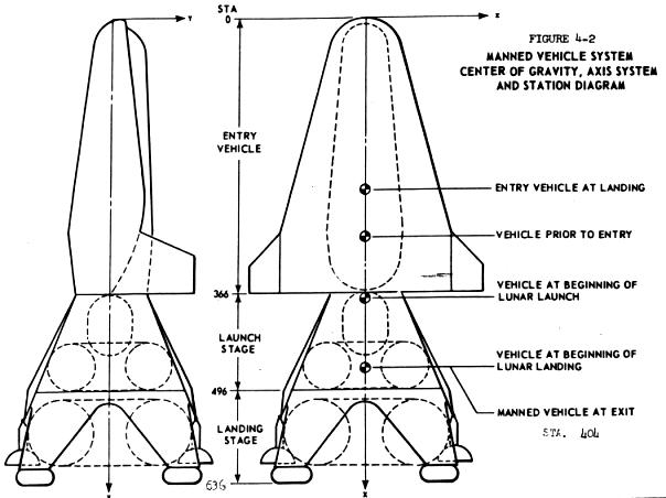 Lunex Lunar Lander Two view drawing of Lunex Lunar Lander, showing centre of gravity and coordinate system stations. |
Present level of technology is such that a satisfactory flight vehicle power system will be available when required for the Lunex mission. Additional development effort should be initiated in certain specific areas, such as a reliability evaluation program for fuel cells and an investigation of the problems of operating chemical dynamic systems in the zero G environment.
Close co-ordination must also be maintained with the manager of project 3145 (U) Energy Conversion, to insure the availability of the required secondary power sources.
4.2.5 GUIDANCE AND CONTROL SYSTEM
4.2.5.1
A study of the guidance and control requirement for the lunar vehicle indicates that the mission can be accomplished by reasonable extensions of present state-of-the-art equipment. The complete lunar vehicle guidance package should be capable of furnishing guidance and control during the following phases of the lunar mission.
Ascent and Injection
Outbound Mid-course
Lunar Landing
Lunar Ascent
Inbound Mid-course
Earth Re-entry
Earth Landing
Present state-of-the-art equipment is capable of handling portions of the guidance and control problem associated with the above phases of flight. However, in order to obtain a complete guidance and control system, it is felt that development of the following items should be undertaken.
4.2.5.2 INERTIAL PLATFORM
Guidance requirements for both the manned and unmanned vehicles can be met with the use of guidance concepts based on the use of inertial and corrected inertial data in a combination of explicit and perturbation computations of present and predicted trajectories. Consequently, an inertial platform configuration suited to the space environment is needed. This platform should be light in weight, highly reliable, and capable of maintaining a space-fixed reference over a long interval of time. Present gyroscopic devices and accelerometers are neither accurate nor reliable enough to accomplish the space mission.
An inertial platform which holds great promise for use in lunar missions is one utilising electrically suspended gyros in conjunction with advanced accelerometers capable of operating in a space environment. Present electrically suspended gyros are capable of operating with a drift rate of .0005 deg/hr/g and it is anticipated that by 1966, a drift rate of .0001 deg/hr/g will be attainable. Also, no difficulties are foreseen in maintaining suspension of the rotating member in an acceleration field of 15 G's with 30 g's being possible. Development of a small inertial platform utilising electrically suspended gyros will be required for the lunar mission.
4.2.5.3 STAR TRACKER
In order to increase the reliability and the accuracy of the inertial platform, a compact star tracker for use with the platform during the outbound and inbound mid-course phases of the lunar flight is desired. Also, the star tracker should be capable of operating in a lunar environment so that it can be used for stellar alignment during the lunar launch portion of the mission. The accuracy of present solid state star trackers is approximately 10 seconds of arc and their weight is approximately 15 pounds. However, these trackers are untested in a space environment and must be developed for the lunar mission and for use with the small inertial platform. In particular, the star tracker must be capable of furnishing accurate stellar alignment information to the inertial platform during the lunar ascent portion of the mission. If it is possible to develop a controllable thrust engine in time to meet the launch schedule, the boost and injection guidance problem for the lunar ascent will be simplified as it will be possible to time-control a predetermined velocity path. This development could possibly reduce the accuracy requirement of the star tracker.
4.2.5.4 LONG BASELINE RADIO NAVIGATION
Since manned as well as unmanned flights are planned for the lunar mission, it is necessary to have a navigation system to back-up the inertial system and to increase the over-all accuracy of the guidance and control techniques. Long baseline radio/radar tracking and guidance techniques offer great possibilities for tracking and guiding vehicles in cislunar apace. Present studies show that there are a number of problems yet to be solved to give the long baseline radio navigation the desired accuracy. Among these problems are 1) the accuracy with which co-ordinates can be determined for each tracking station, 2) the accuracy with which corrections can be made for tropospheric and ionospheric propagation effects on the system measurements, and 3) the accuracy with which "clocks" can be synchronised at the several stations. Reasonable extensions of the state-of-the-art should be able to overcame these problems however, and it is felt that the development of a long baseline radio navigation system will be necessary for the lunar mission.
4.2.5.5 DOPPLER RADAR
Anticipation that radio beacons will be in place on the lunar surface has somewhat simplified the lunar landing phase of the mission. The use of mid-course guidance will enable the vehicle to approach the moon within line-of-sight of at least one of the radio beacons, and the beacon can be utilised for the approach phase of the lunar landing. However, for final vertical velocity measurement, a sensing technique particularly sensitive to small velocity changes is required. A small CW Doppler radar is ideally suited for this requirement. Therefore development of a small, reliable Doppler radar which can operate in the lunar environment is needed. In order to decrease the power requirement for the radar it should not be required to operate at a range of over 300 miles.
4.2.5.6 RE-ENTRY GUIDANCE
Major emphasis must be placed on the guidance requirements for the re-entry phase of the lunar mission. Position, velocity, and attitude can be measured by the inertial system, however, other measurements initially required will be temperature, temperature rate, structural loading and air density. Extensive further study is needed to define these measurements with any accuracy. Early earth return equipment should furnish the data necessary to develop the required re-entry guidance package for the lunar mission.
4.2.5.7 ADAPTIVE AUTOPILOT
The control of the re-entry vehicle mill require an adaptive autopilot due to the wide variation in surface effectiveness. Adaptive autopilots such as used in the X-15 are available, but extensive development is needed to ready them for use in the lunar mission.
4.2.5.8
The following projects or specific tasks within these projects can be utilised to provide the development required for the Lunex program.
4144 (U) Guidance and Sensing Techniques for Advanced Vehicles
40165 (U) Data Conversion Techniques
50845 (U) Guidance Utilising Stable Timing Oscillators
50899 (U) Molecular Amplification Techniques
4427 (U) Self-Contained Electromagnetic Techniques for Space Navigation
4431 (U) Inertial System Components
44169-II (U) Space Adapted Celestial Tracking System
44169-III (U) Multi-Headed Solid State Celestial Tracker
44169-IV (U) Solid State Celestial Body Sensors
5201 (U) Inertial Systems Technique
5215 (U) Military Lunar Vehicle Guidance
50820 (U) Military Lunar Vehicle Guidance Systems
58821 (U) Military Lunar Vehicle Terminal Guidance
4.2.6 COMPUTER
4.2.6.1
The United States has the ability to provide a suitable computer facility at the present time to support the Lunex mission. As the milestones in the program are realised and requirements become more complex, the computer capability will improve to meet these more stringent requirements. Detailed studies on the specific needs of the missions, time-phased, will be conducted to determine trade-offs among possible techniques to insure that machine sophistication does not became an end unto itself. The following guidelines providing adequate flexibility, have been followed in arriving at the required development recommendations:
a. Manned vehicles will require extensive data reduction to give an operator real-time displays of the conditions around him and solutions to problems such as, velocity and attitude corrections, etc.
b. Sensor control (aiming and sampling rate) and data processing will be accomplished on the vehicle either on ground command, or by operator direction.
c. Mid-course and terminal guidance requirements will make severe demands upon vehicle-borne computational systems.
d. Radiation hazards and effects which are unknown at present could influence the technology that will be utilised for lunar missions.
e. Emergency procedures must be available in the event that the operators became incapacitated and incapable of returning to earth at any time during the mission.
4.2.6.2
The computer capability can be expanded in two basic ways by improved hardware, or new concepts. Examples of new approaches which will be reviewed prior to selection of the final vehicle design are the following:
a. Standardised computer functions incorporated into modules so that they can be used to "build" their capability for each mission required. Such a concept would allow a vehicle designer to fabricate a computational facility without resorting to extensive redesign and/or re-packaging. The modularised concept noted above is particularly adapted to unmanned missions.
b. For a manned mission two fixed programs could be permanently placed in storage; these would be an overall command, or executive routine to direct the sequences of operation, and the other could be an emergency return-to-earth routine that could be actuated by the master control. Thus a 5-pound tape unit would replace a larger core memory and provide a higher degree of flexibility. The principal advantage in this system is that the computer is general-purpose in design and therefore useable on a large variety of missions and unnecessary capabilities will not be carried on a particular mission.
c. An optimised hybrid of analogue and digital devices combined to use the better features of each, i.e., speed of problem solution from the analogue and precision, flexibility, and data reduction from the digital.
4.2.6.3
Substantial improvements in computer capability, developments, reliability, volume, weight, and power consumption will be available for the Lunex program by effort expended in the following areas:
a. Core-rope memories to be used in fixed memory applications.
b. Functional molecular blocks. By 1963, the date of earth orbit, it is expected that more than 80% of all computer functions can be performed by this method. Advantages are numerous: high memory densities, extremely small size, small weight and power consumption.
c. Self-healing, or adaptive programming techniques as a means for back-up on component reliability.
d. Electroluminescent-photoconductive memory devices should be considered for their radiation and magnetic invulnerability. In this regard, pneumatic bistable elements should be considered for the same reason.
e. Photochromic storage devices have advantages in high storage densities, 1 billion bits/cubic inch. Certain applications, such as semi-permanent storage, could benefit from this feature.
4.2.6.4
The following projects in the Applied Research Area will be utilised to obtain improvement in computer technology:
3176 (U) Space Borne Computation & Control Techniques
4421 (U) Digital Computation Methods & Techniques
DEVELOPMENT - TEST - PRODUCTION
4.2.7 COMMUNICATIONS
4.2.7.1
The manned lunar mission will require communications channels between the vehicles and earth and on the lunar surface for telemetry, T.V., voice, and vehicle control. Specific system parameters will depend on the characteristics of the ground tracking network and communications stations which will be used to support the lunar missions.
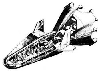
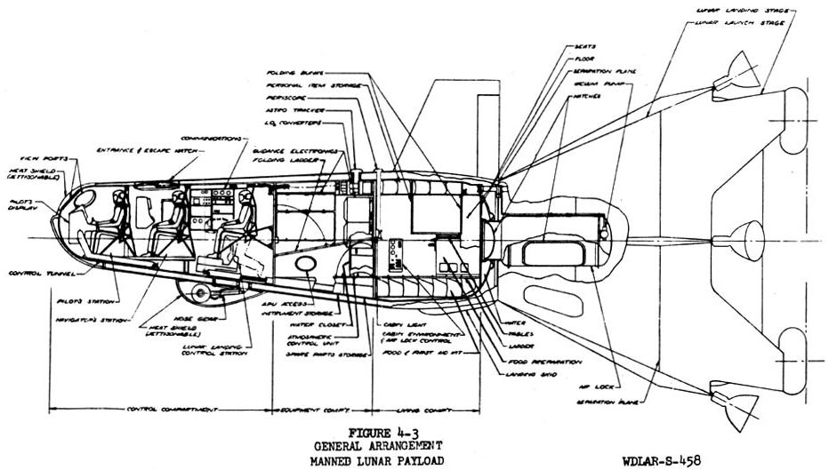 Figure 4-3 Inboard Profile of Lunex Spacecraft |
There are no significant technical problems associated with the development of equipment to perform the required communications operations. One exception to this general statement is that during re-entry radio transmission may not be possible at the lower frequencies utilised elsewhere in the mission because of the plasma shield set up by aerodynamic heating. One possible solution may be to provide a separate system operating at 10,000 mcs for re-entry. Overall savings in equipment weight, and power requirements will result from careful analysts and identification of requirements for information transfer and maximum utilisation of system components in a dual role. This will be done during the vehicle design phase. While not a requirement for early missions the capability to provide a secure communications link is desirable and will be considered during final design of the communications systems. A secure communications link will be a requirement in later missions. Throughout all phases, communications links critical to mission success should incorporate a high degree of protection against natural or man-made interference, or deliberate jamming.
4.2.7.3
The following Air Force projects will be reviewed and used to provide the necessary results required for the Lunex mission:
4335 (U) Applied Communications Research for Air Force Vehicles
4519 (U) Surface & Long Range Communications Techniques
5570 (U) Communications Security Applied Research
4.2.8 ENVIRONMENTAL DATA
4.2.8.1
Present knowledge of the lunar environment is extremely limited and it is necessary to obtain detailed information concerning the lunar composition, subsurface structure, surface characteristics, meteorite flux, level of solar and cosmic radiation, and magnetic field. This knowledge is required to design the equipment for the Lunex program so that personnel may be protected and the mission accomplished.
4.2.8.2
The importance of lunar composition in manned exploration of the moon lies largely in the ability of the moon to provide fuel for vehicles and secondary power, as well as to supplement life support systems with additional water, radiation shielding material, and semi-permanent shelters. Of these lunar resources, water appears to be of major importance both as a fuel and in life support. Water will probably be present both as ice in permanently shadowed zones and as water of hydration in certain minerals such as serpentine.
4.2.8.3
Present knowledge of lunar composition is almost entirely theoretical. The relatively low lunar density (3.34) indicates low metal content. By analogy with the compositions of meteorites it is generally assumed that the moon is composed of chondritic (stony meteorite) material. That this assumption is only partially valid is demonstrated by the fact that chondritic meteorites would have to lose about 10% of their iron content in order to attain this lunar density.
4.2.8.4
The Air Force and NASA are presently trying to determine the lunar composition indirectly through study of tektites, which may be fragments of the moon, and through study of micrometeoritic dust captured above the atmosphere. (Air Force efforts are funded under Project 7698).
4.2.8.5
The Air Force is trying to determine the lunar composition directly by means of spectrometric analysis of the natural X-ray fluorescence of the moon due to the bombardment of the lunar surface by solar radiation. The first knowledge of lunar composition is anticipated in March of 1962. (This work is also funded under Project 7698).
4.2.8.6
NASA intends to measure the lunar composition directly by means of its Surveyor lunar probe now scheduled for mid-1963.
4.2.8.7
Neither Air Force measurements of overall lunar composition, nor NASA measurements of spot compositions will satisfy the requirement for location of lunar resources. The NASA Prospector vehicle scheduled for 1966 will obtain more widespread data, but that is urgently needed is detailed knowledge of the variation of lunar composition over the whole surface. This can only be accomplished by a lunar orbiting vehicle with appropriate instrumentation. NASA presently has this planned for 1965 and the appropriateness of their instrumentation remains in doubt. Also this is too late to meet the requirements of the Lunex program.
4.2.8.8
The importance of lunar subsurface structure in exploration of the moon lies largely in a possible collapse hazard under vehicles and personnel, and in the possibility of utilising subsurface structures as shelters and storage facilities.
Present knowledge of lunar subsurface structure is based on a theoretical extrapolation from the presumed origin of the surface features. The majority of lunar geologists believe that lunar craters were formed by means of the impact of large meteorites, and that only limited volcanism has occurred in the lunar highlands. The maria, on the other hand, are thought to be giant lava pools; although the melting is assumed to have been triggered by asteroidal impact.
Based on these theories of origin for the lunar surface features, it is thought that the subsurface structure of the lunar highlands will consist largely of overlapping layers of debris ejected from the impact craters. The collapse hazard of such material is negligible. The maria should be covered by no more than 40 feet of vesicular (bubble filled) lava, with maximum vesicle (bubble) size about six feet in diameter. Such terrain could present a collapse hazard, the severity of which will depend upon actual (rather than maximum) vesicle size.
It should be noted, however, that a rival theory for the origin of lunar craters holds that they were produced by volcanism as calderea. Should this theory be correct, the collapse hazard in the highlands would probably exceed that on the maria.
In order to determine the lunar subsurface structure, it is necessary to place instruments on the moon. Thus, the Air Force, although contributing theoretical evaluations an described above (under Project 7698), has no program for directly determining lunar subsurface structure. NASA plans to place seismometers and a coring instrument in the Surveyor vehicle in mid-1963 to determine these parameters. Again, point measurements are not sufficient, and geophysical instrumentation adequate for determining subsurface structure from the lunar orbiting vehicle (1965) should be developed.
4.2.8.9
The importance of lunar surface characteristics lies in their critical importance in design of both rocket end surface vehicles and in lunar navigation. Critical surface characteristics include gross topography, microtopography, and the nature of the lunar dust. Of these characteristics, knowledge of gross topography will be important in overall rocket design and in design and operation of rocket landing and navigational equipment. The microtopography (relief less than 20 feet) will be important in the design of rocket landing equipment and the vehicle for surface exploration. The nature of the surface dust will be moat important in design of the vehicle for surface exploration.
Present knowledge of gross topography shows that slopes are generally gentle, and topographic profiles have been determined over a limited amount of terrain. Present knowledge of microtopography is very limited. Radar returns, once thought reliable indicators of low microrelief, are now considered by moat space scientists to be so poorly understood that conclusions may not be drawn from them. Photometric data appears to indicate a rather rough surface, but this data is also subject to more than one interpretation. Present knowledge of the nature of the lunar dust is entirely theoretical. The leading school of thought holds that the dust is compacted and sintered. An opposing school holds that the dust bears an electrostatic charge. Should the dust bear an electrostatic charge, it would be very loose and probably subject to migration. The hazard to surface vehicles and even personnel is apparent.
Gross lunar topography on the visible face is presently being mapped by the Aeronautical Chart and Information Center based on techniques developed under Project 8602. Maximum resolution is about 1/3 mile, and average resolution is about one mile. Higher resolution photography and photography of the back side of the moon will be obtained by the lunar orbiting vehicle planned by NASA for 1965. A co-operative effort by ACIC and NASA is presently envisioned to produce the necessary topographic lunar charts.
Microtopography is being studied by the Army Corps of Engineers through radar experiments. (the Air Force work is being done on the Millstone radar equipment) The nature of the lunar dust is being studied primarily by the Air Force under Projects 7698 and 8602 by means of radiometrlc studies from high altitude unmanned balloons and results are anticipated in early 1962. NASA anticipates obtaining at least partial data on the nature of the dust from Surveyor (mid-1963) by television observation of the lunar surface and by the landing characteristics of the vehicle.
4.2.8.10
The meteorite flux and level of solar and cosmic radiation near the lunar surface are important for the survival of personnel either on the lunar surface or in vehicles and shelters.
Present knowledge of these parameters is fairly precise as a result of satellite and deep space probe experiments by NASA and the Air Force. Only the radiation environment within the first few meters of the lunar surface is still speculative as a result of uncertainties in our knowledge of the interaction of solar and cosmic radiation with the lunar surface materials. It seems likely that a cloud of ions will be produced by radiation bombardment as well as secondary X-rays. The density of the electron cloud is unknown, and may be critical for lunar communications.
The Air Force is studying the lunar and cislunar radiation environment under Projects 6687, 6688, 7601, 7649, and 7663 by means of satellites, deep space probes, and vertical sounding rockets. The NASA Surveyor vehicle (mid-1963) should give detailed knowledge of the radiation environment at the lunar surface.
4.2.8.11
The lunar magnetic field may be important to space and lunar surface navigation, and in its effects on ionised lunar materials.
The Russian Lunik II indicated that the lunar magnetic field must be very small. The Russians were not clear on how small, but it is generally thought that the moon does not possess a magnetic field. Thus, all magnetic effects should be derived from the very low intensity interplanetary field and magnetic fields, "frozen" into solar plasmas.
The Air Force is studying the interplanetary magnetic field under Project 7601. NASA should be able to determine the field near the lunar surface by means of the Ranger vehicle during 1962, and the field at the surface by means of Surveyor (mid-1963).
4.2.8.12
Two facts are apparent from a study of the data outlined above. First, one Air Force project (7698), which was funded for only 250K in 1962 and 300K in 1963, is responsible for moat of the research on the lunar environment. More funds are required for a speed-up in this program. Second, many critical experiments are tied to the NASA lunar orbiting vehicle, which has not been considered a very important vehicle by NASA. This program is essential to the Lunex and should be speeded up and planned more carefully.
4.2.8.13
Effort on Air Force Project 7698 will be increased substantially to insure that data necessary for the Lunex mission is available. A close working relationship will be established with NASA to provide, if possible, the inclusion of Air Force requirements in their planning for lunar programs both as regards to objectives and scheduling.
4.2.9 MATERIALS
4.2.9.1 The lunar expedition imposes rigid requirements on materials to maintain their characteristics while subject to radiation, vacuum, temperature extremes, and meteorites. This problem must be considered by the individual subsystem design. It is intended to point out here the overall material problem and programs which will contribute to its solution.
4.2.9.2 The absence of an atmosphere on the moon increases the radiative flux (particle and electromagnetic) from the sun and as such potentially increases the possibility of damage to man and lightweight plastic structures through the formation of free radicals and subsequent depolymerisation. The need for lightweight shielding is apparent. The vacuum conditions of the moon would aggravate the problems associated with moderately volatile constituents of plastics, lubricants, etc. For instance, the relatively volatile plasticizers in a plastic material could evaporate and interfere with the plastic function. Finally, the results of impact of micrometeorites on structural materials must be determined. All desirable properties must be acquired without penalty of weight. In addition to the problems encountered on the Moon, similar problems are encountered while in transit. In particular the heating encountered on re-entry into the Earth 'e atmosphere at 37,000 feet per second presents a severe material problem.
 Figure 4-3 Overhead view of Lunex Spacecraft |
a Lubricants that will function for long periods of time in a vacuum and temperature conditions such as exist in the moon.
b. Materials that will not sublimate in a vacuum at moon temperature.
c. Light-weight shielding material against meteorites.
d. Light-weight radiation shielding.
e. Shock-absorbing material that will function at 330 degrees F.
f. Coatings that will resist radiation, especially during periods of solar flares.
g. Glues and adhesives that will function with lunar materials.
4.2.9.4 Present projects to raise the level of technology in materials are listed below. They will be supported as required to insure success of the lunar mission.
7312 (U) Finishes and Materials Preservation.
7320 (U) Air Force Textile Materials.
7340 (U) Non-Metallic & Composite Materials.
7351 (U) Metallic Materials.
7371 (U) Applied Research in Electrical, Electronic, and Magnetic Material.
7391 (U) Energy Transmission Fluids.
4.2.9.5 While work in the basic research program cannot be counted on to provide technical breakthroughs within the time schedule of the Lunex program, materials study of this type will be monitored so that all technical advances can be integrated into the Lunex program. Specific examples of projects of this type are:
8806 (U) Research on Materials at High Temperature.
7022 (U) Surface and Interface Phenomena of Matter.
9760 (U) Research in Properties of Matter.
4.3 TEST PLAN
The development and production of the equipment for the Lunar Expedition will require a concurrent and detailed test program.
The test program will be carried out on the basis of research tests to establish design criteria, materials tests, component tests, and finally, a progressive series of tests as components are assembled into subsystems and major systems and structures. Integration tests for flight suitability will be conducted for all functioning systems and the complete vehicle. Payload effects on the booster structure will be determined with a simulated payload. Subsequently, a flight-type payload will be used to demonstrate booster-payload system compatibility, reliability, crew safety, and mission performance.
Emphasis will be placed early in the program on research tests to derive basic design criteria, define the configuration and determine aerodynamic parameters.
Tests are to be run at progressively higher levels as the design evolves. Thus, entire subsystems, combined subsystems and complex major structures are to be subjected to evaluation tests as necessary to investigate component and subsystem interactions, or to prove out complex structural designs.
A captive test vehicle firing program will be the culmination of ground development testing. The over-all objective of the captive-firing program is to demonstrate satisfactory integration of the propulsion system with other vehicle systems that have an interface, direct or indirect, with the propulsion system. The early tests will be conducted in a simulated vehicle with the airborne vehicle systems installed on a heavy-wall propellant tank section. The tanks will be supported by a test stand structure which will also restrain the tanks against propulsion system thrust forces. For final testing a flight-type configuration will be used during captive tests.
Flight testing of the High-Speed Re-entry Test Vehicle, the Abort System, and Orbital, Circumlunar and unmanned lunar landing and Return Vehicles will complete the development program.
4.3.1 TEST CATEGORIES
4.3.1.1 RESEARCH TESTS
Tests will be run in appropriate research laboratories to define basic design criteria in at least the following technical areas:
a. Propulsion
b. Heat transfer
c. Aerodynamic forces and pressures
d. Materials
e. Statics (structures)
4.3.1.1.1 Propulsion Tests -- Wind and vacuum tunnel testing will be conducted to investigate the problems of multiple re-start in a vacuum environment, to develop throttleable techniques, to determine lunar landing problems, and to determine the desirability of using the same engines for lunar landing and lunar launching.
Tests will be made to evaluate the propulsion stage for the circumlunar flights and to determine the capability of the abort propulsion system to accomplish its objective.
4.3.1.1.2 Heat Transfer Tests -- Testing will be required on the insulation for the liquid hydrogen tanks to determine:
a. Optimum material thickness and weight
b. The amount of liquid hydrogen boil-off
c. the air leakage through seals
d. The airload effect on structural integrity
The thermal bowing of insulation panels
f. The separation distance between panel and tank skin
Scale-model or modified full-scale air-conditioning tests will be conducted on engine components, adapter sections and flight equipment storage areas.
Heat transfer characteristics for selected materials, structures, and surfaces will be required to support the engineering design.
4.3.1.1.3 Aerodynamic Force and Pressure Wind-Tunnel Tests -- Wind-tunnel model tests of the launch vehicle and payload configuration will be required to accurately determine the aerodynamic forces and moments imposed on the vehicle during the boost trajectory.
These tests will provide data for determination of structural design criteria, aerodynamic stability and control parameters, and the performance penalty incurred by aerodynamic drag. The test program will include both force and pressure measurements through the flight Mach number range for which these effects are significant.
Wind tunnel testing of selected shapes at velocities never before studied will be necessary to determine re-entry vehicle characteristics. Particular emphasis will be placed on control surface capability and heating problems. Manoeuvrability limits, g loadings, re-entry corridor characteristics and subsonic landing characteristics must be determined in support of the engineering design program.
Integration and correlation of the ground wind-tunnel testing with the high-speed re-entry flight test program is essential.
4.3.1.1.4 Material Tests -- A materials development test program will be undertaken to determine the allowable design strength values and provide design information on the selected structural materials over the appropriate temperature ranges for the base metallic, ablative surfaces, and welded joints. Particular emphasis will be placed on tendency toward brittle fracture under service conditions and in selecting materials for re-entry at 37,000 ft/sec. The testing program will consist of at least the following:
Materials.
a. Smooth and notched static tensile tests of the selected materials.
b. Static tensile tests of welded joints, both fusion- and resistance-welded, for the selected joint configuration for each type of sheet material.
c. Smooth and notched static tensile tests of the selected extrusion and forging materials.
d. Notched impact tests of the extrusion and forging materials.
e. Low-cycle, high stress fatigue tests of welded joints made by the fusion and resistance methods for the selected joint configurations in sheet materials.
This data will be accumulated for the appropriate temperature ranges, i.e., from elevated re-entry temperatures to the cryogenic temperatures in the tanks, as dictated by the projected environmental requirements. In addition, supporting tests such as metallographic examinations and chemical composition determinations will be made as required.
4.3.1.1.5 Static Tests -- static test program will include design load structural substantiation testing to demonstrate structural integrity of the Manned Lunar and Cargo Payloads.
Structural substantiation testing to design loads and temperatures will be accomplished on a full-size stub tank, identical (except for length) to the Lunar Landing Stage tank. This will ensure that load introduction and takeout will be representative of the flight article.
One complete interstage adapter will be tested to ultimate design loads under appropriate environmental conditions. The adapter will be attached to a stub tank identical to the Lunar Launching Stage tank section in every respect except length, to ensure realistic load introduction and takeout.
A stub tank will also be used to demonstrate the integrity of the Lunar Launch Stage tank construction under design loads and environments. Methods of introducing the payload vehicle loads into the adapter section and thus the Lunar Launch Stage tanks will be determined.
Tests will also be run on full-size tank bulkheads. These will be attached to a segment of typical tank structure, adequate to allow the bulkhead behaviour to be representative of that of the flight article under design conditions. These bulkheads will be tested to ultimate design loads to ensure their structural reliability at all points within the flight regime.
Ground handling equipment tests will cover critical fittings and joints for structural substantiation of these items under design conditions.
4.3.2 DESIGN EVALUATION TESTS
Component design evaluation testing is defined here as informal testing conducted by the vehicle contractor, or vendor test labs, for the purpose of basic design evaluation prior to production release, sad to pinpoint critical areas in prototype packages.
Qualification testing is defined as those formal tests performed on flight-type hardware to demonstrate compliance with design specifications. A qualification test plan will be prepared approximately 90 days after engineering go-ahead outlining the qualification test conditions. The qualification tests are to be performed in strict accordance with written and approved detailed test procedures, and witnessed by the Air Force, or an approved representative.
The vehicle contractors' test laboratories will conduct these tests, or subcontract and supervise them at an independent testing agency. Components to be tested will be determined during the engineering design effort.
Controlled environmental conditions will simulate conditions that airborne and ground support equipment are expected to experience during manufacturing, shipping, storage, pre-flight and flight.
Environmental testing conditions will be established based on data already obtained in research and development programs on large rocket-powered vehicles and associated support equipment. Conditions for shipping, storage and handling environmental tests are established in current military and commercial specifications. Subsystem, combined subsystems, and structural evaluation tests will be run in appropriate laboratory faculties to investigate component and subsystem interactions, and to prove out structural designs. Acceptance test procedures will also be developed for use in the factory on deliverable hardware.
A test plan describing the basic conditions and test objectives of each factory systems test, along with the checkout parameters and recorded evaluation data, will be prepared.
A final acceptance test will be required at the time the contractor delivers the vehicle to the Air Force. Test conditions will be as close to the flight conditions as is feasible and safe. All systems will be energised and operated simultaneously.
A final acceptance test evaluation document will be prepared for use by the Air Force and the contractor in determining compliance with test requirements.
Systems acceptance test procedures will be based on all critical parameters required to determine proper functioning of each system in accordance with design specifications and drawings. This will assure a co-ordinated effort of vehicle design, test equipment design, and factory acceptance testing.
4.3.3 FLIGHT TESTING
The Lunex flight test program represents a long and expensive effort leading to the first manned landing on the moon. It requires basic research flights, equipment checkout flights, capability demonstration-flights and finally, the manned and cargo Lunar Expedition flights. This type of effort can only be achieved efficiently and at a minimum cost if the end objective is always clear and the program is designed to meet this objective.
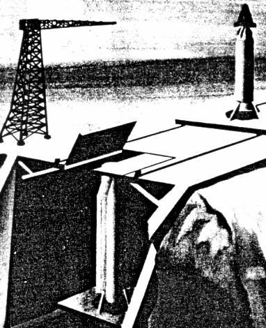 Lunex Launch Pad Lunex Launch Pad with BC-2720 vehicle in assembly. The Lunex upper stage package has been integrated with the 'B' stage and will be installed by crane on the C-2720 booster and core stage assembly already installed in the cliff-side pad. |
The flight test program is summarised on the Lunar Expedition Test Schedule. The following major objectives will be accomplished in the indicated part of the test program.
4.3.3.1 HIGH-SPEED RE-ENTRY FLIGHT TEST
Since present wind-tunnel capabilities are limited to approximately 18,000 ft/sec., it is necessary to perform re-entry flight testing at velocities that range from 25,000 to 45,000 ft/sec. The major objectives of this test program are to:
a. Verify or disprove present theories on basic re-entry techniques as extrapolated to the stated velocity range.
b. Determine problem areas and develop new fundamental theory, numerical procedures and testing techniques where required for this re-entry range.
c. Identify the following:
(1) Items that can be investigated further on a laboratory scale.
(2) Specific laboratory facility requirements.
(3) Additional flight tests that must be performed.
d. Support the engineering design program for the Lunex by providing the above data and special shape testing if required.
4.3.3.2 Lunex RE-ENTRY VEHICLE FLIGHT TEST
The Lunex Re-entry Vehicle will be flight tested by various techniques and in varying environments. Each test will be designed to allow the vehicle to proceed to the next more difficult step. The major testing steps are presented below, with the major test objectives for each step.
a. Prototype Drop Test
Prototype vehicles will be drop tested from a B-52, or equivalent, in both an unmanned and a manned series of tests. Each series will be designed to:
(1) Establish landing characteristics.
(2) Measure inherent subsonic, transonic, and hypersonic stability and control characteristics of the vehicle.
(3) Explore the flight characteristics of the re-entry vehicle in every possible portion of the Mach number spectrum.
(4) Train Lunex crews.
b. Orbital Test:
Maximum use will be made of SAINT orbital test information and unmanned and manned flights will be accomplished. These tests will demonstrate:
(1) The capability of the Lunex Re-entry Vehicle to operate in the orbital area.
(2) Re-entry capability at velocities of 25,000 ft/sec.
(3) The manoeuvrability of the re-entry vehicle and its capability to land at a pre-selected earth base.
c. Circumlunar Test
This flight will use the Circumlunar Propulsion Stage and the Lunex Re-entry Vehicle. The major test objectives are:
(1) To send an unmanned and then a manned vehicle around the moon and return to an earth lending at a selected base.
(2) To check out guidance, flight control, guidance, communications and life support sub-systems in a true space environment prior to landing on the lunar surface.
(3) To perform manned reconnaissance of the lunar surface.
d. Lunar Landing and Return
The unmanned vehicle flights will check out the Manned Re-entry Vehicle and related systems to provide a completely automatic system before man first tries the most difficult step in the Lunex program. The major test objectives for these flights will be to:
(1) Check out the Lunar Landing and Lunar Launching Stages.
(2) Check out the Cargo Payload's ability to deliver cargo packages to a preselected site on the lunar surface.
(3) Place three men on the lunar surface so that the initial surface reconnaissance can be accomplished prior to the arrival of the Lunar Expedition.
4.3.3.3 LUNAR LAUNCH STAGE FLIGHT TEST
The Lunar launch Stage will be initially checked under orbital conditions to:
a. Demonstrate space environment operation.
b. Demonstrate engine restart after "soaking" in apace for an extended period.
c. Demonstrate automatic checkout, communications, and remote control capability.
The Lunar Launch Stage will then be flight tested with the complete Manned Lunar Payload for the unmanned and manned Lunar Landing and Return Missions.
4.3.3.4 LUNAR LANDING STAGE FLIGHT TEST
The Lunar Landing Stage will be initially checked out by drop testing. These tests will:
a. Demonstrate landing techniques and the capability of the selected landing system.
b. Evaluate the effects of unexpected terrain variation.
c. Determine the effects of malfunctioning equipment during the landing manoeuvre.
d. Evaluate the effects of engine blast on landing surfaces similar to the predicted lunar surface.
The Lunar Landing Stage will receive its first space evaluation in orbit. The major objectives are:
a. Correlate drop-test data with orbital or space operations.
b. To determine the effects of space environment on the stage.
The first Lunar Landing with the Lunar Landing Stage will be accomplished with a Cargo Package as the payload. When this has been completed a Lunex Re-entry Vehicle will be landed unmanned. The test objectives are to:
a. Demonstrate the feasibility of landing large cargo packages on the lunar surface.
b. Demonstrate the feasibility of automatically landing a "manned vehicle" while unmanned.
c. Provide a man-rated system for the Lunar Expedition.
4.3.3.5 CARGO PACKAGE CONFIGURATION
Various configurations for the Cargo Package of the Lunex Cargo Payload will be tested. The objectives are to:
a. Determine the Cargo Payload aerodynamic characteristics.
b. Demonstrate that the Cargo Packages can be delivered where desired on the lunar surface.
4.3.3.6 ABORT SYSTEM FLIGHT TEST
The fact that a system of this magnitude must possess some measure of "unreliability" is recognised and a "fail safe" abort system is required to insure the survivability of the crew. The test objectives for the Abort System Flight Test Program are to:
a. Demonstrate that crew members in the manned Lunex Re-entry Vehicle can be recovered safely in the event of a malfunction.
b. Demonstrate that the Space launch System is capable of shut-down, or thrust vector change, so that crew abort is possible.
4.3.4 CHECKOUT AND TEST EQUIPMENT
The test equipment will be fully automatic with quantitative readout capability for all critical functions. The Lunex checkout equipment will be the same, or compatible with the Space Launching System checkout equipment. The equipment will be capable of checking out the complete booster and payload system as well as any individual, or isolated component, or subsystem. It shall be fully capable of checkout of any one stage, or the re-entry vehicle, as an isolated unit, and will mate with the stage interface functions and furnish appropriate operational or simulated error inputs to the stage systems.
For the time period of interest, it ii entirely practical to incorporate malfunction prediction capability for preventative maintenance. This will entail a computer function which will accurately control and record the input and output signal values to each system or component. Variations in operation will be recorded and compared to predetermined failure values or characteristics and will forecast the remaining service life of the system under test.
The checkout equipment shall be installed in each blockhouse and it may be used in conjunction with the launch area. This same equipment shall be utilised in the vehicle manufacturing checkout and test functions, as well as in the launch complex, receiving inspection, and maintenance facilities.
The blockhouse equipment will monitor the launch control system commands and inputs as well as those of the payload. Because the launch control equipment will display only go/no-go signals, the checkout and test system will furnish quantitative displays of any function under question for human appraisal and decision.
When the systems are flown unmanned and on the early manned lunar flights it will be necessary to provide automatic checkout where appropriate via a telemetry link. As an example, prior and during lunar launch the checkout procedures will be monitored at the earth control station via the telemetry link.
4.4 PRODUCTION PLAN
At the present time a detailed Production Plan is not available. However, the present preliminary design study will be completed on 30 June 1961 and the final report to be provided by six independent contractors will include their proposed Production Plan. When the study results have been evaluated a Production Plan for the Lunar Expedition will be prepared .
Several points are apparent at this time and they are presented for completeness in this plan.
4.4.1 QUANTITY
Limited quantities of early equipment will be required until the test program improves and increases the capabilities of each item and production quantities became possible. Then, as development and testing proceeds the equipment will become more standardised and production techniques will become more applicable. When the Lunar Landing and Return flights are initiated it will be necessary to launch vehicles at rates that vary from one to two flights per month. When the Lunar Expedition is actually underway the launch rate will remain at a rate of two per month for an extended period. Considering the size, weight, complexity, and importance of these vehicles this represents production rates even when compared to past aircraft or missile production programs.
4.4.2 QUALITY
The inherent reliability of the systems required for the Lunar Expedition program will be maximised by good design practice. Reliability testing represents a major effort of the test program, but the achieved reliability of these systems can only be maintained during production by an excellent quality control program. This means that good organisation, adequate manning and early recognition of the quality control problem is essential. Close co-ordination is required between the quality control personnel and the reliability personnel in the design, development, and test program if the reliability program and the test results are to provide the proper guidance so that quality can be maintained throughout the production effort.
4.4.3 LOCATION
It is anticipated that most of the major systems and sub-systems can be manufactured at facilities, or locations presently in existence and available to the aerospace industry. However, the possibility does exist that certain items, such as the first stage solid propellant stage, may be manufactured at the Lunar Launch Complex due to its size and transportation limitations. These particular items have not been specified at this time, but this will be done as soon as possible.
SECTION V. BUDGET AND FINANCIAL
5.0 INTRODUCTION
The funding estimates for the Lunar Expedition Program are based on results obtained from previous concept, feasibility, and preliminary design studies. These results were published in Lunar Observatory Final Report, Volume I - Study Summary and Program Plan, numbered AFBMD TR 60-44 and dated April 1960. The costing of this program was accomplished by the Rand Corporation and was based on a completely integrated program.
The funding estimates for the Lunar Expedition represent all the costs of establishing a habitable facility on the moon except the cost of developing the Space Launching System.
This funding would include a Lunar Transport Vehicle development program that would give the US the capability of using the moon and space. Then if the need should develop in the future, the Lunar Expedition Facility could be expanded to support military operations. Studies have shown that the moon possesses real military potential and it could support a recallable deterrent capability. The development of the Lunar Transport Vehicle represents a minimum program for the Air Force to obtain control of the cislunar volume and the lunar surface.
5.1 BUDGET ESTIMATE AND FINANCIAL PLAN
A preliminary design for the Lunar Transport Vehicle is presently being accomplished by six contractors on an active study program. This program was funded for $300,000 in FY 61 and three of the contractors are each performing the design under a $100,000 contract. The other three contractors are participating on a voluntary basis. The final reports for this preliminary design will be submitted to the SSD on 30 June 1961. Evaluation of these reports will follow immediately and the results will be used to revise this document where necessary The Lunex program has an Engineering Design competition scheduled for initiation in January 1962. This competitive effort would be evaluated and a decision on the manufacturing approach would be possible by January 1963. To accomplish this program the following funds will be required:
 Lunex BC-2720 LV Lunex BC-2720 launch vehicle installed on the pad. |
FY-63: $ 112.2 million
Should the above funds not be made available, the schedule for establishing the Lunar Expedition will be delayed proportionally to the delay in funding.
Launch Facilities
Expedition Costs
5.2 COST ESTIMATES
The funding requirement for the complete Lunex Program are as follows:
| Item | 1962 | 1963 | 1964 | 1965 | 1966 | 1967 | 1968 | 1969 | 1970 | 1971 |
| R & D | 26.9 | 104 | 335 | 660 | 1084 | 1608 | -- | -- | -- | -- |
| Launch Facilities | -- | 8 | 64 | 64 | -- | -- | -- | -- | -- | -- |
| Expedition Costs | -- | -- | -- | -- | -- | -- | 1135 | 1023 | 798 | 631 |
| Annual Total | 26.9 | 112 | 399 | 724 | 1084 | 1608 | 1135 | 1023 | 798 | 631 |
| Program Total | 7541 |
To accomplish the Lunex Program, addition information about the lunar surface is required at an early date. This means lunar surface photographs from a lunar orbiting vehicle and the delivery of a radio-light beacon to the lunar surface by a soft landing vehicle. Present NASA programs will provide some information and capability. However, to meet the Lunex program schedule, the following additional funding will be required by either the NASA or the Air Force:
| Item | 1962 | 1963 | 1964 | 1965 | 1966 | 1967 | 1968 | 1969 | 1970 | 1971 |
| Lunar Photographs and Radio-Light Beacon | 15 | 75 | 85 | 15 | -- | -- | -- | -- | -- | -- |
| Recovery of Lunar Core Sample | 12 | 35 | 85 | 285 | 265 | 85 | 24 | -- | -- | -- |
| Annual Totals | 27 | 110 | 175 | 300 | 265 | 85 | 24 | -- | -- | -- |
5.3 FY 62, 63 FINANCIAL PLAN
| FY-62 | FY-63 | |
| MANNED LUNAR PAYLOAD | ||
| Lunex Re-entry Design & Mock-up -- (2 cont'r, 8 M ea) | 16,000 | 80,000 |
| Lunar Landing Stage -- (2 cont'r, 1 M ea) | 2,000 | 10,000 |
| Lunar Launching Stage -- (2 cont'r, 1 M ea) | 2,000 | 10,000 |
| SECONDARY POWER | ||
| Manned Vehicle Power System | 600 | 1,000 |
| Surface Vehicle Power System (15 kW) | 100 | 300 |
| Nuclear Lunar Facility Power (300 kW) -- (Spur Program Support) | 1,000 | 1,500 |
| GUIDANCE | ||
| Mid-course System | 200 | 450 |
| Lunar Terminal System | 300 | 450 |
| Lunar Ascent System | 100 | 300 |
| Earth Return System | 200 | 500 |
| LIFE SUPPORT | ||
| Crew Compartment Design | 400 | 1,000 |
| Ecological System | 1,000 | 1,200 |
| Moon Suit or Capsule | 500 | 800 |
| COMMUNICATIONS & DATA HANDLING | ||
| Manned Vehicle Video System Design | 400 | 1,000 |
| Wide Band Moon-Earth Link Design | 200 | 400 |
| Secure Narrow Band Link Study | 100 | 300 |
| Man-Man Lunar Surface | 300 | 650 |
| Materials and Resources | ||
| Re-entry Materials Research | 1,000 | 1,300 |
| Lunar Natural Resource Dev. | 500 | 1,000 |
| Total In Thousands | 26,900 | 112,150 |
6.0 MANAGEMENT FOCAL POINT
The focal point for management of the Lunar Expedition Program will be a Lunex Program Office within the Space Systems Division, AFSC. The Director of the Program Office will co-ordinate, integrate, monitor and direct all activities of the Lunex Expedition Program. Subordinate to the Director will be managers for major parts of the program. A tentative organisational chart for the Program Office is shown in Figure 6-1.
6.1 RESPONSIBILITIES
a. The Earth Launch Complex Office will be responsible for the civil engineering aspects of building up the earth launch base. The immediate problem of this office will be a site selection survey.
b. The Earth Launch Vehicle Office will be responsible for all earth launch boosters required for this program.
c. The Lunar Landing and Launch Vehicles Office will be responsible for all development and testing of the Lunar Landing Stage and Lunar Launch Stage.
d. The Manned and Cargo Payloads Office will be responsible for the development of the manned Lunex Re-entry Vehicle and the Cargo Package. This will be one of the key offices in the entire program since it will be concerned with such major technical areas as life support equipment, re-entry problems, secondary power and structures.
e. The Communications and Data Handling Office will be responsible for establishing the communication network and centralised data handling organisation. It will also concern itself with communications problems between the earth, the moon, and the Lunex Re-entry Vehicle and point-to-point on the lunar surface.
f. Guidance and Flight Control office will be responsible for developing: ascent, mid-course, terminal, lunar ascent, and re-entry guidance equipment.
 Lunex Figure 6-1 Lunex Program Office |
h. The Plans Office will be responsible for examining other potential uses of equipment developed for the Lunex Program. For example, the same equipment could be used for sending men around Mars and Venus, or perhaps effecting a landing on Phobos. Considerable planning also needs to be done regarding the exploratory phase of the Lunar Expedition.
i. Programming Office will be responsible for scheduling and budgeting of the entire program. This office will have under its control a network of computers designated as the PEP program.
j. The Technical Integration and Support Office will be responsible for insuring the technical compatibility of all components of the system, such as, that the vibration is within tolerable limits during the boost phase when all components of the system have been put together. This office will also provide technical assistance to each of the main component offices. The component offices such as the Manned and Cargo Payloads Office will not rely entirely on the Technical Integration and Support Office for assistance, but will be free to obtain the best technical advice available in the nation from whatever source is necessary, such as other government laboratories or universities. This Technical Integration and Support Office will be manned by Air Force officers who will be responsible for the various disciplines and for technical support from the Aerospace Corporation.
k. The Reliability Office will insure that a strong reliability and safety program is followed by all contractors throughout the program. Since reliability and safety is of such extreme importance in this program every effort must be made to insure the reliability of the final equipment. This can only be done by giving proper recognition to the. problem at a high organisational level where policies and recommendations can be recognised and implemented.
6.2 PROGRAM OFFICE MANNING
A Program Office must be established immediately after program approval if planned schedules are to be met. It is estimated that an initial build-up to 72 officers plus 35 secretaries will be required. A requirement for 100 MTS will be established with the Aerospace Corporation. In view of the magnitude of the program, which will build up to more than one billion dollars a year, a larger Program Office will be required. Planning for these increased manpower requirements will be accomplished by the Program Office, after it is established. Suggested initial distribution of personnel within the Program Office is as follows:
a. Lunex Program Director 4
b. Plans 4
c. Programming 6
d. Technical Integration and Support 20
e. Reliability 2
f. Earth launch Complex 5
g. Earth Launch Vehicle 5
h. Lunar Landing and Launch Vehicle 5
i. Manned and Cargo Payloads 15
J. Communications and Data Handling 3
k. Guidance and Flight Control 3
6.3 ORGANISATIONAL RELATIONSHIPS
There will be a continual and energetic exchange of direction and information between personnel of the Lunar Program Office and development contractors. Because of the complex nature end magnitude of the program, the Program Director will be required to deal with many contracts from diverse technical areas. It is envisioned that an associate contractor will be selected for each major portion of the program, who will, in turn, use many supporting contractors of various technological capabilities. Technical integration and support will be accomplished by the Aerospace Corporation under the overall guidance and control of the Program Office.
6.4 AIR FORCE DEVELOPMENT AND SUPPORT
The Lunex program office will work with the Technical Area Managers within AFSC. The Technical Area Managers have project responsibility for development of solutions to technical problems such as those associated with guidance, materials, rocket engine propulsion, life support, etc. Each Technical Area Manager will identify and emphasise those critical technical problems to which specific effort must be directed in order to attain a capability required by the Lunex program.
6.5 OTHER AGENCIES
Specific arrangements will be made with other agencies as requirements arise in the development of the Lunex program.
6.6 MANAGEMENT TOOLS
The basic philosophy of developing all elements of this program on a concurrent basis introduces rigid scheduling requirements. Specific tasks must be defined and scheduled. However, when development problems dictate that many factors be varied to keep abreast of advancing state-of-the-art, concurrency and even the end objectives are affected and possibly delayed. A management tool which uses an electronic computer will be used to support the Program Director in planning, operating, and controlling the Lunar Expedition Program. It will be initiated in the early stages of the program and continue to be used throughout the expedition phase. This management tool, called Program Evaluation Procedure (PEP) will assist the Director by providing:
a. A method of handling large masses or data quickly, efficiently and economically..
b. The capability to locate, identify and this correct trouble spots.
c. The capability of integrating the many varied and complicated facets of the Lunar Expedition Program.
6.7 PEP
The PEP management tool is made possible through the use of an electronic digital computer. The scheduling and monitoring of many thousands of items required in the Lunar Expedition Program make the use of this computer technique imperative. The PEP approach employs linear programming techniques with a statistical concept in conjunction with the electronic computer. This procedure facilitates the analysis of interrelationships of many thousands of program elements. The results are presented as program summaries upon which the Director can base decisions. (See Fig. 6-3)
The first step in using the PEP management tool is to make a detailed analysis of the overall Lunex Program. Each major event, milestone, or accomplishment that must be achieved is listed in chronological order. The events must be well defined and should occur at an instant of time which can be identified. A network, or a program plan chart, is laid out in which the events are shown as points or circles whose positions roughly represent their chronological order. Interrelationships between the events (circles) and sequence of events are shown by connecting lines. The line between the events represents work that must be done to proceed from one event to the next (See Figure 6-4). The computer then totals all of the expected activity times along every possible (in the thousands) route of the network from start to the end event. The PEP computer then examines the total times of the large number of paths in order to find the longest, which is called the critical path. The critical path defines the sequence of events which will require the greatest expected time to accomplish the end event.
The effects of a delay for any particular milestone or event an the entire program or on any other event can be quickly and efficiently determined so that corrective action can be taken if required.
7.0 PRODUCTION
It is intended that this program use two significant concepts that will result in better management of the materiel support program. These are the Delayed Procurement Concept and the Responsive Production Concept. Under the Delayed Procurement Concept, the ordering and delivery of high-cost insurance-type spares is deferred until the final production run must be made, allowing for the accumulation of maximum operational experience with the new item before a final spares order must be placed. Under the Responsive Production Concept, a portion of the requirement for high-cost operational spares is procured in unfabricated, unassembled form. When the spares demand can be more reliably predicted, based on actual usage experience, additional complete spare items can be produced within a very short lead-time period. When experience fails to justify a requirement for additional complete spares, the materiel and parts involved can be utilised in end article production. The policy shall be to buy minimum quantities of high-value spares and maintain close control over their transportation, storage, issuance, and repair until they finally wear out, or are no longer required. Simplification of procedures and relaxing of restrictions on low-value items will provide the means (man-power, machine time, etc.) for more precise management of high-value items.
7.1 SUPPLY
Maximum utilisation will be made of existing assets. Where practical, equipment and parts will be reclaimed from completed test programs, repaired, modified and overhauled to suitable condition for use in later tests and operational tasks. The procedures and paperwork involved with procurement of spare parts must be streamlined to permit maximum flexibility in planning and responding to a continually changing configuration. Immediate adjustment of inventories and reorder points must result from test program and engineering changes. Selection of spare parts should be made at the time of initial design to enable procurement of spare and production parts concurrently to eliminate reorder costs resulting from separate procurements.
Determination of quantities, reparable-overhaul modification planning, control etc., shall be accomplished and directed by a permanently organised and active group composed of personnel representing the engineering, production, materiel, reliability, quality control, procurement and contract departments, and the various affected sections within these departments such as design, test, planners, etc., attending as required. The AFPR will have a member assigned to this group for surveillance purposes and to provide logistic guidance on problems which may require advice from the Air Force.
Persons assigned to the group shall be well qualified by reason of experience and technical ability.
The procedures and paperwork involved shall be streamlined, taking due cognisance of the powers and capabilities of the above group to permit maximum flexibility in planning and the quickest possible response to changes and emergency situations.
The group will pay particular attention to control of hi-value items and items critical to the needs of the expedition and test program. Such items, particularly those potentially subject to imminent redesign, will be rigorously screened to assure economical inventory and the best possible repair, overhaul and modification planning at all times.
The group shall be responsible for the following:
a. Immediate adjustment of inventory and reorder points resulting from changes to the delivery schedule, the test program, and for engineering changes.
b. Inventory review and adjustment of initially established stock levels and/or reorder points in light of latest experience gained from the test program every time reorder or minimum stock levels are reached.
c. Review of stock levels, and adjustment or disposition of non-moving items on a continuing basis, but at intervals not to exceed sixty (60) days for any individual hi-value items and 180 days for other items, or at other internals as agreed upon by the Contractor and the Contracting Officer. This is to include the return to production of any surplus quantities for rework to later design requirements.
d. Control of repair overhaul modification planning.
7.2 DISTRIBUTION
The Contractors shell develop internal working procedures which encompass the following requirements:
a. Inventory levels shall be programmed to vary with anticipated utilisation. Shipments in advance of estimated requirements will not be made except when it is clearly in the best interest of the program to do so.
b. Stock levels shall be minimised by maximum economical reliance on repair, overhaul, and modification of reparable items. Repair, overhaul, and modification turn-around time will be a prime determinant in establishing the minimum stock level period for each item.
c. Where feasible (with particular emphasis on hi-value and critical items), inventory cost will be minimised by stockage of repair, overhaul and modification spares, pieces and components (relatively low-cost items) in conjunction with a pre-planned and flexible expedited repair, overhaul, and modification program, as opposed to stocking sub-assemblies and end items themselves (the relatively high-cost items).
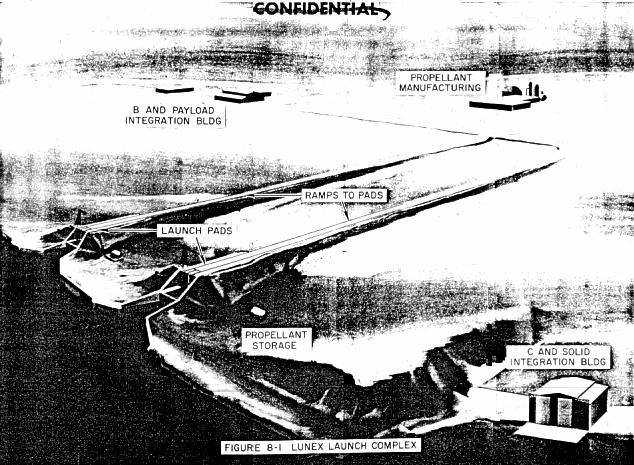 Lunex Figure 8-1 Lunex USAF lunar lander launch complex. The B stage and Lunex manned glider or Cargo payloads would be integrated in the buildings, moved to the cliff-side launch pads, and then stacked on the core and booster stages. |
7.3 STORAGE
Parts, whether required for the test or expedition programs, should not be segregated from production stock. This merely adds an unnecessary stockage cost burden. By combining storage facilities with a commingling of stock, considerable cost savings can be effected. Spares and production stock serve as buffer stocks for each other. If multiple activities such as manufacturing, test, and the expedition are supplied from a single storage facility the chance of stock-out would be minimised.
7.4 REAL PROPERTY INSTALLED EQUIPMENT (RPIE)
Each contractor is charged with the responsibility of identifying, as well as determining the criteria for all items required for successful mission accomplishment. When the requirements have been determined the responsibility for accomplishing the required RPIE materiel support program will be assigned. This materiel support will include the necessary selection of spare parts to be stored at the manufacturing facility or at the launch site.
7.5 MAINTENANCE
The proposed operational mode of the Lunex program is unique in that it retains all the features of a research and development program. In the time period designated as "expedition", it can be expected that in addition to a variety of missions the systems will be modified and improved, the launch facilities and support equipment may require modification, and technical development may force program changes. Since the expedition period is actually a continuation of the development and test program it is apparent that the systems and techniques developed during testing may also be continued for the Expedition.
An evaluation mill be made to determine the feasibility of having contractors support the program throughout its entire life. However, in determining the total task, consideration must be given to the available Air Force manpower, equipment and facilities that may be used to support the Lunex program.
7.6 MANUFACTURING FACILITY CRITERIA
The equipment production facilities will preferably consist of an existing large aerospace plant convertible to Lunex production with a minimum modification program. It may be necessary to build a faculty that is adjacent to, or easily accessible to navigable waterways. The facility should obviously be located in an area containing an abundance of skilled manpower. Manufacturing Test Facilities adjacent to the manufacturing facilities would be very desirable to reduce transportation problems.
Certain items, such as the large liquid and solid boasters and propellant, will probably be assembled at the Lunex Launch Complex and special facilities for manufacturing these items will be required at the launch complex. Thus checkout and acceptance test facilities will also be required at the launch complex.
Many major manufacturing items, such as the Lunar Landing Stage and the Lunar Launch Stage, will be produced at the manufacturers' facility. This will require propellant storage, or a propellant manufacturing capability at the plant, plus various test and check-out facilities to support manufacturing.
As an example, the following test facilities will be required to support the manufacturing of the Lunar Landing and Lunar Launching Stages:
a. Configuration -- For each of the two stages a Propulsion Test Vehicle Test Stand and two Flight Acceptance Firing Stands will be required. In addition, cold flow test facilities consisting of one pad and three structural towers will be required.
The separate test complexes will dedicated one for each of the two stages. There will be only one centrally located blockhouse with control and instrumentation capability for operating both complexes. Each hot firing stand would be located in accordance with a 2 psi explosion overpressure criteria. An explosive force calculated on equivalent LH2 caloric content to TNT, shows that the hot stands should be no closer than 2000' to any other hot or cold stand.
b. Test Pad Configuration and arrangement -- Each hot test pad will consist of a concrete pad containing the launcher structure. The stage is erected by a mobile commercial type crane, and personnel access for maintenance is by work stand and ladders, or a cherry picker. No service tower will be required.
c. Thrust Level Measurement -- Thrust levels will be determined by measuring the chamber pressure and applying the result to the engine manufacturer's calibration curve. Tanking level is determined by the Propellant Utilisation System.
d. Altitude Simulation Unit -- A plenum chanter, containing steam jets upstream of its exhaust bell, shall be attached to each engine for altitude simulation.
e. Flame Deflector -- The design is a conventional configuration elbow shaped shield cooled with a firex water injection system.
f. Propellant Storage and Handling Equipment -- A central LO2 storage and transfer facility shall be provided for each of the two test facilities. The Lunar Landing Stage facility shall store 350,000 lbs. of LO2. Spherical, vacuum insulated dewars shall be used. The transfer unit shall be a motor operated centrifugal pump with 500 gpm and 100 psi discharge head capacity. The Lunar Launch Stage Test Facility LO2 storage shall contain 18,000 gallons in spherical dewars with a transfer pump capability of 200 gpm and 100 psi discharge head. Distribution lines for both complexes would be prefabricated, static vacuum, insulated steel pipe.
An LH2 storage and transfer facility will be provided at each hot firing test stand and the cold flow test pad. The transfer system is an LH2 gas generator system with air being the thermal source. Pressuring level in each tank would be 100 psi. The LH2 storage capacity requirement for each Lunar Launch Stage facility is 15, 000 lbs. and at each Landing Stage Site is 35,000 lbs. Again the storage facilities would be spherical dewars with segmented, prefabricated, static vacuum insulated stainless steel pipe distribution lines.
8.0 INTRODUCTION
As part of the Lunar Transport Vehicle study, consideration was given to the facility required for the launch and support of the Space Launching System and the lunar payloads. It was assumed that the manufacture of all boosters and the payload would be accomplished at existing factories. Facilities and equipment required for the manufacture of large boosters may be readily installed at factories having clearance sufficient to handle the booster. Large boosters such as required for this program must necessarily be transported over long distances by specially constructed barges. By selecting manufacturing facilities and launch sites adjacent to navigable waters, a minimum of overland transport would be required. A significant saving may be effected by providing launch capabilities at selective areas where existing support facilities, personnel housing, and assured tracking capabilities are available.
The logistic support for the launch rates indicated in this plan dictates that new propellant manufacturing facilities be constructed at the launch site and that transport barges and other vehicles be available to transport vehicle components from the manufacturing plants.
A modified Integrated Transfer Launch System is envisioned for the Lunar Transport Launch System. The size and weight of the Space Launching Vehicle, designated the BC2720, precludes the transfer of the entire Lunar Transport Vehicle after assembly, but the integrated transfer of upper stages and lower stages separately with a minimum mating and checkout on the launch pad may provide increased reliability and appreciable cost saving.
In order to achieve the highest launch pad utilisation possible and to make maximum use of specialised capital equipment and highly skilled manpower, the application of operations research technology will be required. To handle the test load and the complex sequencing requirement presented by the three-stage Space Launching Vehicle plus the Lunar Payload, a computer controlled, integrated launch sequencing and checkout system will be needed. It is desirable to accomplish the maximum amount of systems testing in a protected environment prior to locating the vehicle on the launch pad, and to use the launch pad, in so far as is possible, for its prime purpose, that of pre-flight servicing and launching the vehicle.
8.1 LUNAR LAUNCH COMPLEX
The lunar Transport Vehicle System has a requirement for launch and support facilities suitable for manned lunar flight of a vehicle using a BC2720 Space Launching System. Investigation of the launch pad requirements for a launch rate of two per month indicates that from 4 to 6 launch pads would be necessary depending on the launch site location and the means available for handling the booster. There are no existing launch pads capable of handling this vehicle, nor are there, at this time, facilities capable of conducting static testing of the "C" boaster and the launch of the complete Lunar Transport Vehicle. It is possible that by combining the capabilities for both static firing and launch in two of the pads required, a significant cost saving may be gained and an accelerated test program may be effected. This would provide a capability for the launch of the "C" booster with or without solid boost during R&D flight test and for early test missions of the Lunex Re-entry Vehicle. The development and flight test of the "B" booster is planned at AMR during the development program.
It was assumed in the Lunar Transport Vehicle study that the manufacture of all boosters and the payload would be accomplished at existing factories. New and added facilities and equipment such as large forming brakes, special welding jigs, fixtures and machines, and large processing facilities would be required. In plants of sufficient size these facilities and equipment could readily be installed. Further investigation comparing the relative economics of manufacture at the launch site versus manufacture at existing facilities is required to insure an economical choice.
Assemblies having a diameter exceeding 12 feet or weighing over 200,000 pounds cannot be transported over United States railways. A load of 78,000 pounds is considered to be the limit over selected highway routes. Inasmuch as both the "B" and "C" boosters of the Space Launch Systems have diameters in excess of 14 feet, transport from manufacturing plant to the launch site must be by barge. The large quantities of boosters and the special environmental protection required suggest that specially designed barges be constructed to transport these assemblies. Harbours and docking facilities would be required near the manufacturing facility and at the launch site.
By locating the launch facilities at or near Cape Canaveral for an easterly launch significant savings may be effected. The use of existing administrative capabilities, personnel housing, assured tracking facilities, and technical support areas will provide a saving in costs and in lead-time required for construction of support facilities. Similar gains may be made by locating launch facilities at Point Arguello for polar launch. This does not mean that Cape Canaveral and Point Arguello are the only reasonable locations for the launch site. In fact, by extending the Atlantic Missile Range in a westerly direction across the Gulf of Mexico it is conceivable that a launch site in the vicinity of the Corpus Christi Naval Air Complex would provide the full use of AMR Range facilities with minimum overfly of foreign land masses. Likewise, extension of the AMR Range in a northerly direction to the coast of South Carolina would provide a similar accommodation.
8.2 LOGISTICS
The logistic support for the launch rate as indicated in this study dictates that new propellant manufacturing plants be constructed at the launch site. Existing propellant manufacturing plants are inadequate and the launch rates mentioned would use the full capacity of a separate propellant manufacturing facility.
a. Propellant use rates for a 2 per month launch rate are estimated as follows:
(1) Liquid Hydrogen manufacture: 50 tons per day.
(2) Liquid Hydrogen storage at launch pad: 1.5x10^6 pounds.
(3) Liquid Oxygen/Nitrogen Manufacture: 120 tons per day.
(4) Liquid Oxygen storage at launch pad: 4 x 10^6 pounds.
Barges will be required for transport of boosters from the manufacturing plant to the launch complex.
8.3 AEROSPACE GROUND ENVIRONMENT
 Lunex Figure 8-2 Close-up of Lunex Launch Pad, showing BC-270 launch vehicle being stacked. |
The TNT equivalent of vehicle propellants was estimated in the following manner. The TNT equivalent of the liquid propellants was taken at 60% of the total LOX/LH2 load for all stages. This is the figure currently used at AMR for TNT equivalence for LOX/LH2. In this case, because of the great quantities of propellant involved, this degree of mixing is unlikely and the 60% figure would be conservative. Solid propellants are taken at 100% of the propellant weight. It is also considered that detonation of the solid propellants may cause the subsequent detonation of liquid propellants and vice versa; but, the simultaneous detonation of all propellants is not likely to occur. This philosophy resolves to consideration of TNT equivalents of liquid propellants and solid propellants separately and they are not additive. The TNT equivalent of one of the four segmented solid assemblies is 680,000 pounds. The 60% TNT equivalent of the total liquid propellant load is approximately 1,300,000 pounds. Using the highest TNT equivalent (1,300,000 pounds) the inhabited building distance must be approximately 2 1/2 miles from the launch pad and minimum pad separation must be approximately 1 mile. For an inhabited pad adjacent to a launch operation, pad separation would be 2 1/2 miles. It is obvious that the real estate problem will be extensive. For a coastal location of "C" launch pads up to 18 miles of continuous coast line would be required for a distance of 3 miles inland. These distances can be decreased by creating a buffer between the pads. Locating the launch pads in ravines or indentations in cliff aide launch locations might substantially reduce the land areas required. The selected location and orientation of the integration building and other support facilities to take best advantage of topography would do much to decrease distances and reduce costs.
The repeated launching of similar payloads in the Lunar Transport Launching System and the extended time between launches from each pad indicates that a central launch control for all pads might be desirable. To avoid analogue signal line driving problems and to allow greater distances than normal between the pads and the common blockhouse it is possible to use digital control for launch pad checkout and launch. Analogue to digital conversion would essentially be accomplished at each launch pad and transmitted to the blockhouse via digital data link. With vertical mating, assembly and detailed checkout in the vertical assembly integration buildings, only gross, survey type testing or a simulated countdown and launch would be performed at the launch pad, since test and vehicle subsystem sequencing systems could be installed in both areas. Present day checkout methods, because of the many manual controls and long time spans involved, would not provide sufficient assurance of the high reliability of the complex integrated systems expected in the Lunar Transport Vehicle.
SECTION IX. PERSONNEL AND TRAINING
9.0 INTRODUCTION
This section of the Lunar Expedition Program Plan (Lunex) includes estimated personnel requirements to support the program and presents the training required to accomplish the end objective.
The personnel requirements were derived on the basis of the scope of the complete program and the personnel would be comprised of civilian and military personnel. .
The training program was prepared by the Air Training Command and based on the Lunar Expedition Program Plan.
9.1 PERSONNEL
The accomplishment of the Lunar Expedition Program will have a manpower impact on the Air Force that is quite different than previous programs. The number of personnel actually on the expedition will be relatively small compared to the number of personnel required to support the operation. The actual contractor "in-plant" personnel required to accomplish this program are not included in the following figures. However, a general estimate of the total contractors' effort, based on the average estimated annual expenditure for the complete Lunex program, would be the equivalent of one of our larger manufacturing companies with 60 to 70 thousand personnel. It should also be stated that this effort would undoubtedly be spread throughout the industry and not concentrated in one company and the previous statement is only for comparison.
The military and civilian personnel required to support the Lunex program is estimated as follows:
Space Personnel: 145
- Lunar Expedition (21 men at expedition facility, crew rates of 5): 145
- Lunar Squadron: 100
- Launch Squadron: 873
- Instrumentation Squadron: 293
- Assembly & Maintenance Squadron: 860
- Supply Squadron: 562
- Base Support Units: 639
- Administration: 350
Overhead: 1287
- Range Tracking: 940
- Logistic Support Organisation: 347
9.2 TRAINING PROGRAM
The remaining portion of this section of the Lunar Expedition Program Plan (Lunex) presents the Training Program. It is based on the limited data and information available at the time of preparation. The knowledge gained from the state-of-the art development of this program will of necessity have to be applied directly to the training areas to insure "concurrency" of the programs training development. Further, the training knowledge and experience acquired from current research and development programs must be studied for application to this program.
The concepts and plane projected in this part of the PSPP will be subject to constant revision and/or updating. Use of various simulators and synthetic training devices must be a part of the training program. Identification of the required training equipment and real property facilities to house them must be accomplished early in the program development to insure training equipment and facilities being available to meet the training need dates.
The unique mission of the Lunex program requires a comprehensive and timely source of personnel equipment data (PED). This information is required for space crew end support positions required to operate and maintain the space vehicles and support equipment. Development of such data must be initiated as part of the design effort to reduce the time element for follow-on personnel sub-system requirements.
No effort is made in this section to specify requirements for the Space Launching System since they are delineated in the Space Launching System Package Program.
This section of the Proposed System Package Program was developed under the premise that Air Training Command would be assigned the individual aerospace crew and technical training responsibilities for this program. Therefore, ATC must develop their capability concurrent with hardware development through the engineering design phases to support the expedition.
9.3 PLANNING FACTORS AND GROUND RULES
a. Scope:
This section is conceptual in nature at this time and embodies the basis for the training to be accomplished in support of the Lunar Expedition Program. It includes guidance for individual, field unit, and crew training.
b. Definitions:
(1) Aerospace Crew Personnel:
Personnel performing crew duty in the Lunar Transport Vehicle.
(2) Cadre Personnel:
Those personnel necessary for logistic planning, AFR 80-14 Testing Programs, and ATC instruction and preparation of training materials. The requirements for participation in the testing programs will include test instruments for category testing in accordance with paragraph 5 a (1) and (2), AFR 80-14, and Job Training Standards for the Integrated Systems Testing Program in accordance with paragraph 8 g (3), AFR 80-14.
(3) Main Complement Personnel:
Personnel employed in the receipt, check-out, installation, repair, maintenance and operation of the system.
(4) Support Personnel:
Air Force Logistic Commend personnel required for support functions as well as other agencies' supervisors and planners
(5) Types of Training:
(a) Type I (Contract Special Training). Special training courses conducted by contractors at an ATC installation, contractor facility or any other designated site.
(b) Type II. (ATC Special Training) Special Training Courses conducted by ATC training centres' instructors at an ATC installation, contractor facility, or any other designated site.
(c) Type III. Career training/
(d) Type IV. Special training provided by ATC training detachment instructors at the site or the organisation requiring the training.
(6) Testing Programs:
(a) Component - the testing of the components of a sub-system, such as the guidance package, or ecological package.
(b) Sub-system - components assembled into a sub-system, such as the Re-Entry Vehicle Subsystem and tested as a unit.
(c) Integrated System - the Re-Entry Vehicle, Lunar Launching Stage and Lunar Landing Stage assembled together and tested as a whole system.
c. Assumptions.
(1) The man-rated Lunar Transport Vehicle will be available for use by the Lunar Expedition in 1968.
(2) ATC personnel will observe, participate and study the training programs developed for current research and development programs conducted under other government agencies and/or contractors.
(3) AFR 80-14 will be used as a guide for accomplishing the program testing.
(4) The terminology for normal levels of maintenance, i.e., organisational, field, depot, and shop, vehicle assembly and maintenance as specified in AFLC (AMC) letter MCM, dated 25 July 1960, subject: Standard Maintenance Terms and Maintenance Facility Nomenclature for Missile Weapon Systems will apply.
(5) The Air Force Maintenance policy of maximum maintenance at the lowest feasible level will prevail.
(6) Due to the time phasing of the subsystems, special consideration must be given to the training facilities requirements funding for the Re-Entry Vehicle technical training programs.
(7) Testing Dates:
(a) Start of Component Testing Dates are:
1. Re-Entry Vehicle - June 1963.
2. Lunar Launch Stage - February 1965.
3. Lunar Landing Stage - May 1965.
(b) Start of Subsystem Testing Dates are:
1. Re-Entry Vehicle - November 1964.
2. Lunar Launch Stage - May 1966.
3. Lunar Landing Stage - July 1966.
d. Peculiar Requirements and/or Limitations:
(1) The unique mission of this program makes it mandatory that the following actions be accomplished concurrent with the development of the hardware:
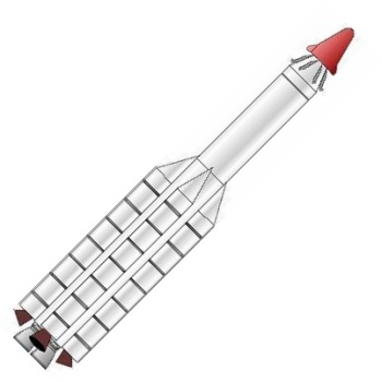 Lunex BC-2720 LV Lunex BC-2720 launch vehicle. |
(b) Type I training dates reflected in the time phasing chart will require the use of R&D and test equipment as training equipment.
(c) Production schedules for R&D and Expedition equipment will include the training equipment required to support Type II and Type III training. Allocation and delivery priorities will be in accordance with AFR 67-8.
(2) An identification of personnel necessary to support this system has been made in order to assist in defining the training parameters. Changes to these estimates will he made as more conclusive information becomes available. See Charts IX A and B.
(3) Maximum Cross-Training will be provided as required to all personnel associated with this program.
(4) The requirement for follow-on training and the value of past experience is recognised and maximum retention of personnel is mandatory.
(5) New and peculiar training problems are envisioned for the technical personnel
(6) The training of the aerospace crew personnel will require the development of a program which is unique to the Air Force.
e. Qualitative and Quantitative Personnel Requirements Information
(1) A QQPRI prepared in accordance with Mil Spec 26239A will be required to develop the training courses, course material and substantiation for the Personnel Classification changes.
(2) ATC and other applicable commands will furnish personnel for the QQPRI integration team and provide technical guidance to the contractor during preparation.
9.4 TRAINING
a. Training Responsibilities and Concepts:
(1) Engineering Design Effort
(a) ATC will participate in the engineering design effort to insure that technical data is collated with the personnel sub-system for follow-on training program requirements.
(b) ATC will be responsible for training required in support, of the R&D effort under AFR 50-9.
(c) Selection of the initial aerospace crew personnel and ATC aerospace crew training instructors for the Lunar Transport Vehicle will commence 8 months prior to the start of Category I Testing.
(d) All Lunar Transport Vehicle crews and military space launching support personnel will be phased into special training (Type I), 6 months prior to Category I Testing.
(e) Environmental, space training for the selected crews and instructor personnel will start 9 months prior to the start of Category II testing and will be conducted by the Aerospace Medical Centre, Brooks AFB, Texas.
(f) ATC Lunar Transport Vehicle crews will be phased out of training 30 days prior to the requirement for Type II or III aerospace crew training to provide follow-on training capability in this area.
(2) Flight Testing & Expedition Program:
(a) ATC will be responsible for all individual training, i.e., technical, aerospace crew, AGE and addition job tasks as required.
(b) All requirements for Type I Special Training, AFR 50-9, in support of this effort will be contracted for by ATC.
(c) ATC will maintain liaison with the contractor concerning engineering changes in the program during its development to keep trainee information in consonance with the program / sub-program configurations and other concepts having a direct implication to training.
(d) Flight Testing & Expedition Crew proficiency will be the responsibility of the Lunex Program Director unless ATC is requested to furnish this training.
9.5 TRAINING PERSONNEL
a. Field Training Detachment (FTD)
The number of personnel required to provide training for lunar vehicle personnel will be determined during the training programming conference. QQPRI, TPR's, Personal Plan, Operational Plan and Maintenance Plan will be available at this time.
b. Contractor Technical Service Personnel (AFR 66-18)
Contractor technical service personnel may be initially required to augment Field Training Detachment (FTD) personnel. CTSP requirements in support of this program will be phased out as blue suit capability is achieved.
c. Trained Personnel Requirements (TPR)
TPR will be developed by commands concerned upon approval of QQPRI, and will be tabulated as gross requirements by command, by AFSC, and by fiscal quarter. These requirements will be phased on anticipated need dates for personnel to be in place at the testing sites, launch sites, and maintenance areas, and will be furnished Hq ATC in sufficient time to allow proper planning for required training.
9.6 TRAINING EQUIPMENT PACKAGE
a. General:
Training equipment requirements will be developed to support:
(1) Check-out and ground maintenance to be performed by the direct support personnel for the Lunar Transport Vehicle.
(2) Flight test operations and maintenance to be performed by the responsible crews. In consideration of this, present and near future systems experience gained in the aerospace area will be applied to the Lunex program to assist in the identification of training equipment. The training for this program must be conducted in the most realistic environment practicable.
(3) Post mission maintenance and test equipment.
b. Equipment Selection:
Selection of training equipment will be based on the following general rules:
(1) Maximum utilisation will be made of training equipment programmed for other missile and space system training programs.
(2) During the initial phases, equipment programmed for test, development, and the expedition programs will be used to the maximum extent practicable when regular training periods can positively be scheduled in the use of that equipment' The lack of availability of such equipment will result in degradation of training.
(3) Equipment selection will be made in consideration of future and/or subsequent programs to provide maximum training capability in similar systems with minimum cost.
(4) Maximum use and development of training films, training graphics, and synthetic training aids and devices will be made to reduce requirements for critical operational items during the initial phases of the program.
(5) Training equipment will be identified in sufficient time to enable procurement and delivery in advance of equipment for use in the flight test and expedition program.
c. Planning Factors:
Planning factors for determination of Training Equipment Requirements:
(1) In view of the limited program information presently available, definitive planning factors upon which over equipment requirements may be based cannot be provided. However, for preliminary planning, the following factors may be applied to subsystems of the program to determine order of magnitude. Provided Control Centres used for other space vehicles will be applicable to the Lunar Transport Vehicle, Category I (Trainers), Category II (Parts / Components / End Items), and Category III (Training Aids / accessories) training equipment requirements as specified in USAF letter dated 30 January 1961, subject: Weapon System Training Equipment Support Policy will be as follows:
Major Vehicle Sections: Percent of Sub-System Cost Required for Training Items
(a) Re-entry Vehicle: 250%
- Complete R/V - 1 ea
- Sub-systems of R/V - 1 ea
- Major components of each sub-system for Bench Items - 1 ea
- Sub-systems of Launch Stage - 1 ea.
- 50% of Major Components for Bench Items
- Major Components - 1 ea
- Complete Cargo Package
- Complete set for handling and testing vehicle sections and included equipment
- Complete set as bench items for maintenance training
(3) Spare parts support will be required for all Category I and II training equipment.
(4) A continuing requirement will exist for the modification of training equipment. These modifications should be provided by review and processing of training equipment change proposals concurrent with operational equipment charge proposals.
(5) Funding of P-400 money will be omitted in consonance with AFR 375-4, Para. 12.
9.7 FACILITIES
a. General:
The needs for training facilities should be established approximately three years prior to the dates at which Type II training equipment will be required. Facilities must incorporate sufficient flexibility to accommodate future updating of training equipment resulting from program configuration changes.
b. Aerospace Crew Training Facilities:
(1) Initial training for aerospace crew personnel will require the use of existing space training facilities. Joint Use Agreements between NASA and other USAF agencies and the Air Training Command will be required to insure maximum utilisation of these facilities. Aerospace Medical Centre's facilities (Brooks AFB, Texas) will be utilised to the fullest. Interservice agreements with the Navy for use of specific training device facilities should be considered for crew training.
(2) The establishment of a centralised space training facility would have a direct bearing on the overall specific requirements for this type of training. The results of the System Study Directive (SSD) Nr 7990-17610, titled: "Centralised Space Training Facility," will have direct bearing on the posture of the training facilities of the future. For this reason, facilities requirements for follow-on training are not projected.
c. Other Training Facilities:
It is anticipated that Technical Training Centres now in existence can absorb the additional technical training load without increasing the facilities. However, modification of existing facilities to provide training laboratories with specialised power and environmental systems will be necessary. This requirement must be identified in sufficient time to permit facility programming through normal procurement cycles.
9.8 BUDGET AND FINANCE
a. Training Equipment Costs
Funding will be required for training equipment identified in Section 9.6, Training Equipment Package.
b. Training Facilities Costs
Funding and costs of training facilities will be determined once the decision is made whether to build a Centralised Space Training Facility or to continue with decentralised procedures. Funding can then be determined for the required facilities and modifications.
CHART IX-B
LUNEX/SPACE LAUNCHING SYSTEM
1. The estimates for the launch system are not included in view of the status of the Space Launching System (SLS) study. It can, however, be estimated that the launch complex personnel utilised in both the liquid/solid propellant type boosters will be integrated into a team for support of this system.
2. At such time as the S.L.S. is designated as the primary launch support system, a PSPP will be made for the launch vehicle and support AFSC's as a part of this program.
SECTION X. INTELLIGENCE ESTIMATES
10.0 INTRODUCTION
The purpose of this section of the program plan is to estimate the foreign threat in terms of technical capabilities and probable programs which may affect the establishment of a lunar expedition. The threat will be defined in terms of major performance capability and dates of operational availability.
10.1 Foreword
The following data was obtained from DCS/Intelligence, Hq ARDC, and published intelligence estimates.
10.2 PERFORMANCE CAPABILITY
The Soviets have flown geophysical and component equipment payloads on their vertical rockets for the development, modification, and acceptance testing of instrumentation for use on their satellite and lunar aircraft. They developed and used complex scientific instrumentation on Sputnik III, and stabilisation, orientation and control equipment on Lunik III and Sputnik IV. Presently, by using their vertical rockets, the Soviets are testing infrared equipment, in addition to collecting data on the background noise level of the earth's surface. It is believed that a development program exists which eventually could lead to detection and reconnaissance satellites. The development program which led to the photographic system used in Lunik III is expected to continue, with an eventual application in photographic reconnaissance and weather satellites.
The Soviet space launch capability is shown in the following table of Sputnik and Lunik booster thrust levels:
- Sputnik I: 300,000 pounds
- Sputnik II: 300,000 pounds
- Sputnik III: 432,000 pounds
- Lunik I, II, and III: 456,000 pounds
- Lunik IV, V, and VI: 466,600 pounds
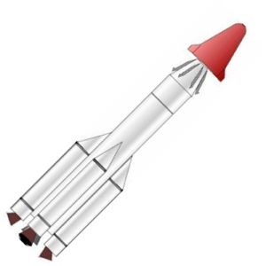
Lunex A-410 LV
Provisional drawing of Lunex A-410 launch vehicle.
- Single engine booster: 1963
- Clustered engine booster: 1965
The maximum Soviet orbit capability, with present ICBM boosters using five (140,000 pound thrust) engines and four (6,600 pound thrust) engines is 10,000 pounds in low altitude orbit. All Lunik and Sputnik vehicles utilised a third stage having 12,500 pound thrust engine burning for approximately 420 seconds.
By using higher energy chemical propellants in modified upper stages, the payload can be increased up to 15,000 or 20,000 pounds during 1961. However, approximately 50,000 pounds of payload may be attained by 1962 if ICBM launch vehicle thrust is increased.
In the 1965-1970 period, a new clustered chemical booster should allow the Soviets to place 50 to 100 tons in orbit in individual launches. This will permit landing a man on the moon.
10.3 SUMMARY AND CONCLUSIONS
Very early the Soviets realised the propaganda value obtainable from space adventures and, accordingly, have striven continuously for "firsts". This has apparently influenced the detailed pattern for their space planning. Even though the Soviets have achieved "firsts" in:
1) Establishment of an artificial earth satellite
2) Rocketing past the moon and placing a vehicle into a solar orbit
3) Hard impact on the moon
4) Photographing the side of the moon not visible from the earth
5) Safely returning mammals and men from orbit
it seems obvious that the Soviet attempts to score "firsts" will continue.
Although large orbiting spacecraft appear to be the prime Soviet technical objective during the period of this estimate, it is believed they will continue to use and improve their current lunar probe capability since there are many "firsts" yet to be accomplished in the exploration of the moon. These include lunar satellites, lunar soft landings, lunar soft landings and return with actual samples of the lunar surface, and, finally, a tankette for a true lunar exploration.
It is expected that the Soviets will continue to launch unmanned lunar rocket probes for the purpose of reconnoitring the moon and near moon environment for the application of this knowledge to the development of manned lunar exploration systems.
Since soft landings are essential for obtaining data on the lunar surface, it is believed that the Soviets definitely will have to develop techniques for achieving lunar soft landings, especially soft landings and return to earth, to establish the procedures to be employed in accomplishing the main objective of establishing a manned lunar station. The first of these test vehicles could be very similar to their Arctic automatic weather stations that presently are jettisoned from aircraft. This vehicle would be able to record temperature, micrometeorite impact, various types of radiation, particle concentration, seismic disturbances, solid resistivity, and depth of probe penetration. As landing techniques are improved, larger payloads with increased instrumentation for terminal control and lunar restart and launch capabilities will undoubtedly be developed.
Circumlunar flights by manned space vehicles, and eventually lunar landings, will be required in order to know more precisely the environmental situation preliminary to the eventual establishment of a lunar base and the complete conquest of this body. This is considered to be a more distant objective of the Soviet program and its attainment will appear, if at all during this decade, toward the end of the period.
Although the landing of a "tankette" on the moon falls under the category of a soft landing, the size and weight of such a vehicle makes it a sufficiently worthy subject for special consideration. The Soviets have published extensively on such a vehicle, and Yu D. Khelbtsvlch, Chairman of the Science Technical Committee for Radio Remote Control of Cosmic Rockets, has published his preliminary design of a tankette laboratory for lunar exploration. Graduate students of Moscow High Technical School now are experimenting with models of a tankette in layers of powdered cement to simulate powdered soil conditions which might be expected on the moon.
Actual accomplishment of the project will have to await the availability and flight testing of the new booster with thrust in the millions of pounds category in the 1965 time period.
The Soviets do not differentiate between military and non-military space systems. They have talked of a peaceful intent of their space program but there are many pounds of payload in their satellites which cannot be accounted for on the basis of data given out. It should be presumed that this could be military payloads. With this in mind, it can be stated that during the early 1970's it is possible that space weapon systems will be developed as a supplement to earth-based delivery systems. It is also possible that military facilities may have been established on or in orbit around the moon. Atmospheric and climatic conditions will demand an air conditioned environment for moon-based delivery systems. For increased survival security and decreased requirements for "imported" construction material, it seems reasonable to assume that these would be constructed under rather than above the moon's surface.
Cargo Package
- The Lunar Cargo Package (See Figure A-1, item e) is that part of the Cargo Payload which represents a package consisting of supplies, equipment, etc., needed on the lunar surface. Preliminary design data implicates that an amount in excess of 40,000 pounds must and can be delivered to the lunar surface.
- The Cargo Payload is that part of the Lunar Transport Vehicle which in placed on a selected lunar trajectory and is boosted to earth escape velocity. It consists of two major parts. These are:
- Lunar Landing Stage
- Cargo Package
- This division is schematically represented in Figure A-1 by the parts labelled b and e. The cargo payload does not include a Lunar Launch Stage since the cargo package remains on the lunar surface. The weight of the Cargo Package is equivalent to the combined weight of the Lunex Re-entry Vehicle (3 men) and the Lunar Launch Stage. The Cargo Payload weighs 134,000 pounds at earth escape.
- A highly elliptical trajectory that goes around the moon and returns to the earth.
- A stage attached to the Lunex Re-entry Vehicle to provide a suitable propulsion and control capability for maintaining the Re-entry Vehicle on a circumlunar trajectory.
- Concept of deferring the final ordering and production of high-cost insurance type spares until maximum flight experience is available.
- A test program using a special Re-entry Test Vehicle designed to obtain fundamental re-entry data and specific configuration data am re-entry velocities of 25 to 45 thousand feet per second.
- A facility designed to be constructed under the lunar surface and to support the Lunar Expedition. This facility will be designed so that it can be readily expanded to support future military requirements.
- The Lunar Landing Stage is that part of the Manned Lunar Payload that will land the Manned Lunar Payload at a selected site on the surface of the moon. The expended portion of this stage is left on the lunar surface when the Lunex Re-entry Vehicle is launched for the return trip to earth (See Figure A-1, item b.).
- The Lunar Landing Stage of the Cargo Payload (See Figure A-1, item b) is identical to the landing stage of the Manned Lunar Payload. It provides the capability of soft landing the Cargo Package at a preselected site. The Cargo Payload is unmanned and the landing operation is automatic. The Lunar Landing Stage remains on the lunar surface with the Cargo Payload.
- The Lunar Launch Complex consists of the base facilities, integration buildings, checkout buildings, launch pads, propellant manufacturing plants, the complex control centre and all of the equipment required to earth launch and support the Lunar Expedition.
- The Lunar Launch Stage (See Figure A-1, item c) is that part of the Manned Lunar Payload that will boost the Lunex Re-entry Vehicle to lunar escape velocity on a moon-to-earth trajectory. It will be ejected prior to earth re-entry.
- The Lunar Team consists of Air Force technical personnel from various Air Force System Command organisations and the various Air Force Command organisations. This team was formed to assist the SSD in establishing a sound Lunar Expedition program. The membership during the past two years has varied from 30 to 50 personnel.
- The Lunar Transport Vehicle is required to transport men and materials for the Lunar Expedition. The Lunar Transport Vehicle consists of a Space Launching Vehicle and one of two payloads. One payload is the Manned Lunar Payload and the other is the Cargo Payload (See Figure A-1).
- Lunex is a short title for the Lunar Expedition Program
- The Lunex Program Director is the individual responsible for directing and controlling all facets of the Lunar Expedition Program.
- The Lunex Re-entry Vehicle (See Figure A-1, item d) is the only part of the Manned Lunar Payload that returns to the earth. It carries three men and all the necessary life support, guidance, and communication equipment that is required. It re-enters the earth's atmosphere and uses aerodynamic braking to slow down and land like a conventional airplane. The preliminary design of the Lunex Re-entry Vehicle calls for a vehicle 52 ft. long with a return weight of 20,000 pounds.
- A vehicle, or system is considered to be "man-rated" when sufficient ground and flight test data has been accumulated to determine that the reliability objectives for the item have been achieved and that the abort system satisfactorily compensates for the inherent unreliability of the system.
- The Manned Lunar Payload is that part of the Lunar Transport Vehicle which is placed on a selected lunar trajectory and is boosted to an earth escape velocity of approximately 37,000 feet per second. It consists of three major parts. These are:
- Lunar Landing Stage
- Lunar Launch Stage
- Lunex Re-entry Vehicle (3 men)
- This division is schematically represented in Figure A-1 by the parts labelled b, c, and d. The complete Manned Lunar Payload weighs 134,000 pounds at earth escape.
- A concept whereby long lead portions of high-cost operational spares are purchased unassembled to reduce costs until final decision is made on spares procurement.
- The complete system, including ground faculties, propellant manufacturing facilities, etc., as required to launch the boosters required for space operations.
AGE
- A term used to describe the Aerospace Ground Environment required for a specified system.
- The Abort System includes all the equipment required to remove, or return the crew members of the Lunex Re-entry Vehicle to a position of safety in the event of a malfunction of the Lunar Transport Vehicle.
- P.E.P. are the initials for "Program Evaluation Procedure". It is a management tool which uses an electronic digital computer. It has the capacity to handle large masses of date quickly. The PEP system provides information that will enable the Lunex Program Director to quickly identify, locate, and consequently, correct program trouble spots.
- A term used to describe Qualitative and Quantitative Personnel Requirements Information that is required to properly plan for personnel training.
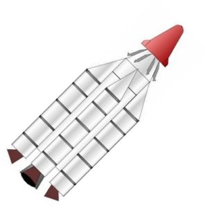
Lunex B-825 LV
Provisional drawing of Lunex B-825 launch vehicle.
- A term meaning Real Property Installed Equipment that is synonymous with Technical Facilities. Technical Facilities are those structural and related items which are built and/or installed by the Corps of Engineers and then turned over to the Air Force or an Air Force contractor.
- A chart prepared to a scale of 1:1,000,000 and covering the lunar surface. Present plans call for the preparation of 144 individual charts to cover the complete lunar surface.
BOSS
- BOSS is the designation for "Biomedical Orbiting Satellite System". The BOSS program uses primates to provide life science data for designing manned space systems.
- The SAINT program will develop and demonstrate orbital rendezvous and satellite inspection techniques. It will further demonstrate the capability of closing, docking, and refuelling.
| Lunex Lunar Lander American manned lunar lander. Studied 1958-1961. The largest single development objective for the Lunex program was to provide a spacecraft capable of transporting men and equipment to the lunar surface and returning them to a selected earth base. |
| Mark I ELSS American space suit, tested 1958-59. The USAF Mark I Extravehicular and Lunar Surface Suit was tested during 1958-59, and led to subsequent development of more refined and satisfactory RX-series "Moon Suits" for NASA. |
Family: Lunar Bases, Moon. Country: USA. Agency: USAF. Bibliography: 16.
| Lunex Chart I - A Lunar Expedition Program Milestone Schedule |
| Lunex Chart III-A Lunar Expedition Master Program Schedule |
| Lunex Lunar Lander Lunex Project Manned Spacecraft |
| Lunex Lunar Lander Two view drawing of Lunex Lunar Lander, showing centre of gravity and coordinate system stations. |
| Figure 4-3 Inboard Profile of Lunex Spacecraft |
| Figure 4-3 Overhead view of Lunex Spacecraft |
| Lunex Launch Pad Lunex Launch Pad with BC-2720 vehicle in assembly. The Lunex upper stage package has been integrated with the 'B' stage and will be installed by crane on the C-2720 booster and core stage assembly already installed in the cliff-side pad. |
| Lunex BC-2720 LV Lunex BC-2720 launch vehicle installed on the pad. |
| Lunex Figure 6-1 Lunex Program Office |
| Lunex Figure 8-1 Lunex USAF lunar lander launch complex. The B stage and Lunex manned glider or Cargo payloads would be integrated in the buildings, moved to the cliff-side launch pads, and then stacked on the core and booster stages. |
| Lunex Figure 8-2 Close-up of Lunex Launch Pad, showing BC-270 launch vehicle being stacked. |
| Lunex BC-2720 LV Lunex BC-2720 launch vehicle. |
 | Lunex A-410 LV Provisional drawing of Lunex A-410 launch vehicle. |
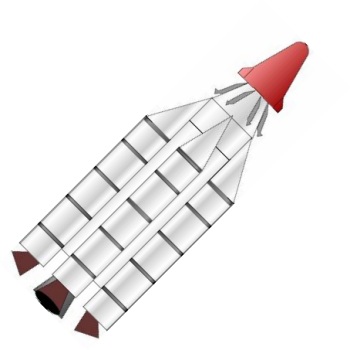 | Lunex B-825 LV Provisional drawing of Lunex B-825 launch vehicle. |
1955 January 1 - .
- Military space projects under study. - .
Spacecraft Bus: Man-In-Space-Soonest.
Spacecraft: Man-In-Space-Soonest,
Lunex.
In 1955-1957 many Air Force officers in widely scattered field units, without coordinated effort, prepared papers and studies proposing military space projects. Small groups at Headquarters Air Research and Development Command, at the Ballistic Missile Division, at Holloman Air Force Base, and at Wright Air Development Center (WADC) sensed danger in the Government's unwillingness to give the new technology the urgent support they felt it deserved. Programs were proposed which called for organized space experiments, "at the earliest practicable date." Such experiments included orbiting satellites, manned and unmanned, a manned space station and a spacecraft voyage to the moon. (Bowen, Lee, The Threshold of Space, Sep 1960, published by the Air Force Historical Liaison Ofc, p.7)
1957 July 29 - .
- Air Force presentation on space capabilities and plans. - .
Spacecraft: Man-In-Space-Soonest,
Lunex.
Air Force Ballistic Missile Division (Western Development Division was redesignated Air Force Ballistic Missile Division, 1 Jun 1957) presented to the Scientific Advisory Board Ad Hoc Committee, meeting at Rand Corporation, a summary of follow on ballistic missile weapon systems and advanced space programs which it was prepared to undertake. These programs included development of high thrust space vehicles capable of earth orbital and lunar flights. (AFBMD Presentation to the Scientific Advisory Board Ad Hoc Committee to Study Advanced Weapons Technology and Environment, 29 Jul 57, prep by AFBMD.)
1957 October 9 - .
- Second generation ballistic missiles and military satellites - .
Spacecraft: Man-In-Space-Soonest,
Lunex.
Scientific Advisory Board Ad Hoc Committee urges development of second generation ballistic missiles and military satellite systems for reconnaissance, communications and weather. The Scientific Advisory Board Ad Hoc Committee on Advanced Weapons Technology and Environment published its review of "... problems of national defense in cislunar space, with particular regard to their impact on future weapons technology and the operating environment in which these weapons might function. " The committee report urged development of second generation missiles not only for their primary weapon system value but for their use as space boosters. The next priority, in the committee's analysis, was to develop military satellite systems for reconnaissance, communications and weather prediction. The Air Force should also plan on reaching the moon and, despite the failure of the committee to define any specific military application resulting from occupation of the moon, appropriate steps should be taken to develop a space technology to support advanced exploration of space. The committee was also concerned that, while it appeared to be the plan of the Air Research and Development Command to place all ballistic missile programs under the management of the Ballistic Missile Division, there was not yet " . . ar official understanding that Air Force Ballistic Missile Division is a permanent organization set up to cover this role into the future." The committee therefore urged that "... Air Force Ballistic Missile Division be recognized at the earliest possible date as a permanent organization for ballistic missiles and satellite projects. " (Rpt of the Scientific Advisory Board Ad Hoc Committee to Study Advanced Weapons Technology and Environment, 9 Oct 57.)
1957 November 13 - .
- Plan for a program leading to the development of man-carrying vehicle systems for space operation. - . Related Persons: Schriever. Spacecraft: Man-In-Space-Soonest, Lunex, . Major General Bernard A. Schriever, AFBMD Commander, directed preparation of a plan for a program leading to the development of man-carrying vehicle systems for space operation..
1957 December 9 - .
- US Air Force recommends immediate goal of landing on the moon - .
Nation: USA.
Program: Lunex.
The Air Force Scientific Advisory Board Ad Hoc Committee on Space Technology recommended acceleration of specific military projects and a vigorous space program with the immediate goal of landings on the moon because "Sputnik and the Russian ICBM (intercontinental ballistic missile) capability have created a national emergency."
1958 January 16 - .
- Aeronutronic concept of an Air Force astronautics program. - .
Spacecraft: Man-In-Space-Soonest,
Lunex.
Representatives of Aeronutronic Systems, Inc. , visited the ballistic missile division to present their concept of an Air Force astronautics program. Their program was based on use of existing hardware and conservative evaluation of new equipment. to be obtained through technical evolution. Test flight of earth satellites and lunar vehicles would acquire necessary data concerning the space environment. Specific goals included biomedical experiments, development of precision orbital flight, recovery and reconnaissance systems, and lunar impact. From this background of successful technical achievement the program would move to manned satellite flights, lunar flights and manned space exploration. This program was designed to lead to manned flight in approximately four to six years. (Memo, Col L., D. Ely, to Col C. H. Terhune, 23'Jan 59, subj: Astronautics Briefing by Aeronutronic Systems, Inc.)
1958 January 24 - .
- Five year plan for an Air Force Astronautics Program. - .
Spacecraft: Man-In-Space-Soonest,
Mercury,
Lunex,
Project 7969.
The Air Research and Development Command convened a committee to prepare a final planning draft of an Air Force Astronautics Program for presentation to Mr. W. M. Holaday. The Air Force proposed five year space program included development of research and test vehicles, satellite reconnaissance systems, a lunar based intelligence system, defense systems, logistic requirements of lunar transport, and strategic communications. If the program wei.accepted in its entirety, $1.156 billion in initial funding would be needed in fiscal 1959. (Memo, Col L. D. Ely, Dir Tech Div, to Col C. H. Terhune, AFBMD, 28 Jan 58, subj: Trip Report.) The Air Force invited the National Advisory Committee for Aeronautics (NACA) to participate in "a research vehicle program to explore and solve the problems of manned space flight. " Specifically, the Air Force objective was to achieve the earliest possible manned orbital flight which would significantly contribute to development of "follow-on scientific and military space systems." An immediate decision was therefore necessary to determine the best approach to the design of an orbiting research vehicle--should it be a glide vehicle or one designed only to accomplish the satellite mission? Inasmuch as both NACA and the Air Force were well along in their investigations of the best approach to be taken in the design of a manned orbiting research vehicle it was suggested that, "These efforts should be joined at once and brought promptly to a conclusion. " Accordingly NACA was invited to collaborate with Air Research and Development Command on an over-all evaluation of relevant space plans and projects and any program resulting from the joint evaluation would be, it was suggested, "managed and funded along the lines of the X-15 effort. " Specific guide lines were furnished the Advisory Committee to facilitate its response to the Air Force request. (Ltr, Lt Gen D. L. Putt, DCS/D, Hq USAF, to Dr. H. L. Dryden, Dir NACA, 31 Jan 58, no subject.)
1958 March 8 - .
- USAF Objective: "Manned Space Flight to the Moon and Return" - .
Spacecraft: Man-In-Space-Soonest,
Lunex.
The Air Force Ballistic Missile Division proposed an over-all space objective about which all other experimental projects would be oriented. This goal was briefly stated as "Manned Space Flight to the Moon and Return. " To achieve this ultimate accomplishment many other space projects and programs would be necessary. The final goal would furnish an objective and a means to develop an integrated space program instead of isolated space ventures whose value might be unrelated to any national purpose. Admittedly, achieving this goal would require much preliminary work and completion of the following programs: Instrumented Satellite Flights and Return; Animals in Satellite Orbit and Return; Biomedical Experiments in Satellite Flights; Man in Satellite Orbit and Return; Instruments and Equipment Around Moon and Return; Animal Around Moon and Return; Instrumented Hard Landing on Moon; Instruments -Equipment Soft Landing on Moon and Return; Animal Soft Landing on Moon and Return; Man Around Moon and Return; Manned Landing on the Moon and Return (Memo, Col L. D. Ely, to Co) C. H. Terhune, 8 Mar 58, subj: Meeting with Hq ARDC Biomedical and Behavioral Sciences Panels, 10-12 Mar.)
1958 April 1 - .
- Lunar photographic atlas begun - .
Nation: USA.
Program: Lunex.
A $61,000 contract was signed by the Yerkes Observatory, University of Chicago, and the Air Force. Gerard P. Kuiper, principal investigator, was to produce a new lunar photographic atlas. The moon's visible surface would be divided into 44 areas, and each would be represented by at least four photographs taken under varying lighting conditions. Additional Details: here....
1958 April 25 - .
- US Air Force manned military space systems program - .
Nation: USA.
Program: Lunex.
The Air Force Ballistic Missile Division published the first development plan for an Air Force manned military space systems program. The objective was to "achieve an early capability to land a man on the moon and return him safely to earth." The program called for the start of a high priority effort (similar to that enjoyed by ballistic missiles), characterized by "concurrency" and single Air Force agency management. The complete program would be carried out in four phases: first, "Man-in-Space Soonest"; second, "Man-in-Space Sophisticated"; third, "Lunar Reconnaissance," exploring the moon by television camera and by a soft landing of an instrumented package on the moon's surface; and finally, "Manned Lunar Landing and Return," which would first test equipment by circumlunar flights returning to earth with instrumented capsules containing animals. Additional Details: here....
1958 April 25 - . LV Family: Thor, Titan. Launch Vehicle: Thor Able, Titan C.
- USAF goal to to "...land a man on the moon and return him safely to earth". - .
Spacecraft: Man-In-Space-Soonest,
Lunex.
The Air Force Ballistic Missile Division published the development plan for an Air Force Manned Military Space Systems Program. The objective was to ". achieve an early capability to land a man on the moon and return him safely to earth. The program represented a reasonable level of accomplishment with a minimum of time and money and called for start of a high priority program (similar to that enjoyed by ballistic missiles) characterized by "concurrency" and single Air Force agency management. The complete program would be carried out in four phases: first, "Man-In-Space-Soonest," was to determine functional capabilities and limitations of man in space by means of earth orbital flights--beginning with an instrumented 2,900 pound re-entry body, then a primate passenger and, finally, a manned capsule. The second, designated "Man-In-Space-Sophisticated," would use a drag type 3, 200 pound re-entry vehicle, capable of a 14 day manned space flight. This device would be used for earth orbital flight only but it would perform experiments essential to the final phase of the lunar program. The third phase, "Lunar Reconnaissance," would explore the moon by television camera and by means of a soft landing of an instrumented package on the moonIs surface. The final phase of the projected program was "Manned Lunar Landing and Return, " which would first test equipment by circumlunar flights returning to earth with instrumented capsules containing animals. At this stage of project development payload capacity would be increased to 9,000 pounds. The spacecraft would then undertake a full scale flight to the moon and safe return to earth with an animal passenger. The climax of the entire project would then be a manned lunar landing, brief surface exploration, and return to earth. This would be followed by other circumlunar flights to fully explore the moon's surface and gather additional physical data. The program was scheduled for completion in December of 1965 at a total estimated cost of $1.5 billion. Program cost estimates were based on use of Air Force rocket hardware and available ground facilities thus eliminating much new development and construction funding. However, new launch vehicle combinations would have to be developed progressing in performance as follows: a Thor-Vanguard second stage, a Thor-fluorine second stage, a "super" Titan with a fluorine-hydrazine second and third stages. Methods of landing involved use of retrorockets to insure a soft landing on the moon and return to earth through re-entry to a predetermined landing area. (USAF Manned Military Space Syst.em Development Plan, 25 Apr 58, prep by AFBMD.)
1958 July 29 - .
- Air Force continued to press for a manned space program. - .
Spacecraft: Man-In-Space-Soonest,
Mercury,
Lunex,
Project 7969.
Despite mounting evidence that the Air Force would not be assigned management of any national lunar program, it continued to press for a manned space program. On this date there was a meeting of Dr. Dryden, National Advisory Committee for Aeronautics; Mr. R. Johnson, Advanced Research Projects Agency; and Secretary of Defense Neil McElroy but future management of a manned space program was not resolved and it appeared that resolution would only bp attained at the Presidential level. It was assumed, however,that the Air Force would have at least $50 million in fiscal 1959 funds to further its space program. (MFR, Col J.D. Lowe, AFBMD, 29 Jul 58, subj: Man-In-Space Program, cited in Chronological Space Hist, 1958.)
1958 September 1 - . Launch Vehicle: Thor.
- USAF space program uncertain due to the creation of NASA. - .
Spacecraft: Mercury,
Project 7969,
Man-In-Space-Soonest,
Lunex,
KH-1.
The future of the proposed Air Force space program was uncertain due to the creation of the Advanced Research Projects Agency and the National Aeronautics and Space Administration. It appeared probable that final over-all space program would be adopted until the large area of overlapping jurisdiction between the two agencies was sorted out. In addition, the Department of Defense was required to transfer some $117 million in fiscal 1959 funds to the National Aeronautics and Space Administration of which $58.8 million was Air Force money. Thus it appeared that of the various proposed programs already within National Aeronautics and Space Administration's legitimate area of interest it might well take over the man in space program primarily because it had the money to undertake its development. In respect to the lunar probe program, the Air Force had to wait for further direction before proceeding further. The large booster (one million pound thrust) authorized for Air Force development was transferred to the civilian. space agency. The Air Force would continue development of the 117L system under the over-all direction of the Advanced Research Projects Agency. (Memo, Col C. R. Roderick, Committee Liaison Div, Ofc of Legislative Liaison, to Asst Dir, Legislative Liaison, Sep 58, no subj.)
1958 November 15 - .
- USAF paper on Space Development Capabilities 1958-1968 - .
Related Persons: Schriever.
Spacecraft: Man-In-Space-Soonest,
Lunex.
At the request of John W. McCormack, Chairman of House Committee on Aeronautics and Space Exploration, Major General B. A Schriever prepared a paper, "Space Development Capabilities 1958-1968" This eloquently projected space advances and goals over the next decade. Schriever pointed out that above developments in any other technical area ". improvements in rocket thrust--our lifting capability -will be a direct determinant of our overall). rate of progress, " To this date the rate of progress in space rested directly on the nation's missile program. Another area of primary concern was increasing the reliability of all elements of a space system. with significant improvements in these two areas the nation could anticipate ever increasing payloads placed in orbit, manned orbital satellites and space stations , lunar flights and near planetary explorations. Recoverable chemical powered boosters, ion beam or thermo-nuclear plasma propulsion systems outer space would open an ent; rely new phase of space exploration. Thus in the months and years ahead it was possible to foresee many dramatic developments in propulsion systems, high thrust space vehicles and a vastly increased knowledge of the space environment. (Paper, "Space Development Capability, 1958-1968, " submitted 15 Nov 58, prep by Maj Gen B. A. Schriever, Cmdr, AFBIVID.)
1959 April 24 - .
- All three military services studying a base on the moon - .
Nation: USA.
Related Persons: Schriever.
Spacecraft: Horizon Lunar Outpost,
Lunex,
Navy SLV,
,
Man-In-Space-Soonest.
Testifying before the Senate Committee on Aeronautical and Space Sciences, Maj. Gen. Bernard A. Schriever, Commander of the Air Force Ballistic Missile Division, stated that all three military services should be studying the possibility of a base on the moon. Up to that point, he felt, all such studies had been "in the blue thinking."
1960 April 9-16 - .
- Detailed lunar charts published by the Air Force - .
Nation: USA.
Program: Lunex.
Detailed lunar charts, consisting of 230 photographic sheets, were published by the Air Force and the University of Chicago Press. The atlas, in preparation under Air Force contract since April 1958, was assembled by Gerard P. Kuiper of the Yerkes Observatory.
1960 May 1 - .
- Contract for signed for lunar surface photography for mapping. - .
Nation: USA.
Program: Lunex.
An additional contract for $10,000 was signed by the University of Manchester, Manchester, England, and the Air Force. Z. Kopal, principal investigator, would continue to work at the Pic-du-Midi Observatory in France, providing topographical information on the lunar surface for the production of accurate lunar maps. The contract (AF 61(052)380) was a continuation of one signed on November 1, 1958, and was to run from May 1, 1960, to October 31, 1960. In addition, the Air Force provided $40,000 for a 40-inch reflector telescope at the Observatory, tremendously increasing its capability for lunar topographical research. By June 1960, information on one-fourth of the visible area of the moon had been produced.
1960 October 17 - . LV Family: Atlas.
- Air Force gives up on separate military man in space program. - .
Spacecraft: Man-In-Space-Soonest,
Mercury,
Lunex.
The Air Force no longer seriously entertained the prospect of a separate military man in space program. Instead the ballistic missile division became deeply involved in support activity for the civilian space agency, especially developing and supplying hardware for the Mercury program. As of this date, Air Force Ballistic Missile Division participation included the following: providing 16 Atlas D boosters to accept Mercury capsules and adapters, to be provided by the space agency, a modified guidance structure, an installed abort system to insure pilot safety, and telemetry. Air Force Ballistic Missile Division also furnished launch facilities at the Atlantic Missile Range Complex 14, and one-half of Hangar J and the necessary modifications thereto as requested and made necessary by booster requirements. Such work included installation of capsule umbilical and checkout cabling, telemetry, communications, and data transfer equipment required by the payload. The missile division also provided the guidance site and use of the range Atlas guidance computer (Mod III) for powered trajectory guidance and the special computations requested by the space agency. Air Force Ballistic Missile Division and several Air Force contractors provided, as of this date, 401 military and civilian personnel to the program. Much of the cost of this support activity was reimbursed by the National Aeronautics and Space Administration, but some was not. Air Force personnel costs, military and civilian; office space and equipment; and normal base support functions were provided at Air Force expense. Cost of a 14 booster "program (the additional two boosters were ordered too late to be included in this summary) was as follows:(Millions of Dollars)
Prior Years FY 61 FY 62 Total Booster Hardware and Launch Service 19.769 15.324 5.924 41.017 Engineering Modifications and Studies, Technical Direction, Booster Safety Program, etc. 3.436 6.367 1.362 11.165 Miscellaneous, Propellant, Transportation, Travel, etc. .466 1.133 .122 1.721 Total Estimate 23.671 22.824 7.408 53.903
(Msg, WDGP 17-10-5, AFBMD to Hq ARDC, 17 Oct 1960)
1960 October 28 - .
- Air Force lunar base briefing to NASA - .
Nation: USA.
Program: Apollo.
Spacecraft Bus: Lunex.
Spacecraft: Lunex,
Man-In-Space-Soonest.
Key staff members of NASA Headquarters and the Commander, U.S. Air Force Research and Development Command, met at the Air Force Ballistic Missile Division, Los Angeles, Calif., to attend briefings and discuss matters of mutual concern.
At an executive session, Air Force and NASA programs of orbital rendezvous, refueling, and descent from orbit were discussed. Long-range Air Force studies on a lunar base were in progress as well as research on more immediate missions, such as rendezvous by an unmanned satellite interceptor for inspection purposes, manned maintenance satellites, and reentry methods. NASA plans for the manned lunar landing mission included the possible use of the Saturn booster in an orbital staging operation employing orbital refueling. Reentry studies beyond Mercury were concentrated on reentry at escape speeds and on a spacecraft configuration capable of aerodynamic maneuvering during reentry.
1961 February 10 - .
- Air Force interest in spacecraft similar to the Apollo - .
Nation: USA.
Program: Lunex.
Spacecraft Bus: Apollo Spacecraft Systems Development Diaries.
Spacecraft: CSM Source Selection.
At the first meeting of the House Committee on Science and Astronautics, during the first session of the 87th Congress, Charles F. Ducander, Executive Director and Chief Counsel of the Committee staff, outlined a number of proposed subjects for study. One subject was the Air Force's interest in a three-man spacecraft similar to the Apollo spacecraft planned by NASA. A Committee staff member had been assigned to investigate this duplication of effort. On February 22, testifying before the Committee, Air Force Undersecretary Joseph V. Charyk stated that the Dyna-Soar program was a direct approach to manned military space applications. The Air Force interest in an Apollo-type spacecraft was part of the post-Dyna-Soar program, Charyk said.
Back to top of page
Home - Search - Browse - Alphabetic Index: 0- 1- 2- 3- 4- 5- 6- 7- 8- 9
A- B- C- D- E- F- G- H- I- J- K- L- M- N- O- P- Q- R- S- T- U- V- W- X- Y- Z
© 1997-2019 Mark Wade - Contact
© / Conditions for Use