
Home - Search - Browse - Alphabetic Index: 0- 1- 2- 3- 4- 5- 6- 7- 8- 9
A- B- C- D- E- F- G- H- I- J- K- L- M- N- O- P- Q- R- S- T- U- V- W- X- Y- Z
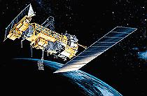
Advanced Tiros N
 Advanced Tiros N Credit: Lockheed-Martin |
AKA: NOAA KLM. Status: Operational 1983. First Launch: 1983-03-28. Last Launch: 2009-02-06. Number: 10 . Gross mass: 3,775 kg (8,322 lb).
The Advanced Tiros N / NOAA KLM satellites replaced operational sun-synchronous polar orbiter weather satellites on-orbit as required to provide continuity to the NOAA-managed operational system. Upon successful achievement of orbit, NASA conducted an engineering evaluation and checkout of each satellite. Upon completion of testing, the satellites were turned over to NOAA for routine operational control. Each spacecraft was designed to meet all on-orbit performance requirements for a minimum period of two years.
Specification
- Mission Life: 2 years minimum required
- Orbit: Sun-synchronous, 833 ± 19 km or 870 ± 19 km
- Mass: 1478.9 kg on orbit/2231.7 kg at launch
- Length/Diameter: 4.18 m / 1.88 m
- Propulsion: Mono propellant hydrazine, GN2 and AKM
- Attitude Control: 3-axis stabilized
- Power: Direct energy transfer
- Thermal: Passive and active controls
- Operation Control: NOAA/SOCC CDA stations at Wallops and Fairbanks. DSN 26-m and AFSCN for contingency support.
- Forward Data Link: S-band command uplink encrypted.
- Return Data Link: Housekeeping telemetry from HRPT and GAC downlinks.
- Science Data Capture: Tape playback direct to CDA (typically eleven 12-minute contacts per day), relayed to the NOAA/CEMSCS in Suitland, MD
- Science Data Processing: NOAA/CEMSCS, Air Force Global Weather Central (AFGWC), International Weather Services and ARGOS
Instrument Payload
Earth imaging was accomplished by the AVHRR/3, a six-channel scanning radiometer, which viewed the same Earth area with each channel. The data acquired during each scan allowed, after ground processing, multispectral analysis of hydrologic, oceanographic, land use and meteorological parameters.
Data from channels l, 2, and 3A were used to monitor reflected energy in the visible and near-IR portions of the electromagnetic spectrum. These data provided means to observe vegetation, clouds, lakes, shorelines, snow, aerosols and ice. Data from channels 3B, 4 and 5 were used to determine the radiative energy from the temperature of the land, water, and sea surface as well as the clouds above them. Only five channels could be transmitted simultaneously, channels 3A and 3B being respectively switched for day/night operation and as determined by operational requirements for the afternoon satellite, while 3B would be on continuously for the morning satellite mission.
For the first time, Channels 1, 2 and 3A on these spacecraft incorporated the low light split-gain provision, providing better resolution in a portion of the radiance range. The Automatic Picture Transmission (APT) mode, using two selected channels, produces a more geometrically linear scan line but at the reduced resolution of 4 km.
The characteristics of the six channels were:
- Channel 1 (Visible): Spectral Bandpass 0.580 - 0.68 micrometers; Spatial Resolution at nadir 1.1 km.
- Channel 2 (Near IR): Spectral Bandpass 0.725 - 1.00 micrometers; Spatial Resolution at nadir 1.1 km.
- Channel 3A (Near IR): Spectral Bandpass 1.580 - 1.64 micrometers; Spatial Resolution at nadir 1.1 km.
- Channel 3B (IR-Window): Spectral Bandpass 3.550 - 3.93 micrometers; Spatial Resolution at nadir 1.1 km.
- Channel 4 (IR-Window): Spectral Bandpass 10.300 - 11.3 micrometers; Spatial Resolution at nadir 1.1 km.
- Channel 5 (IR-Window): Spectral Bandpass 11.500 - 12.5 micrometers; Spatial Resolution at nadir 1.1 km.
Atmospheric Sounding Instruments
Three instruments were used to determine radiance needed to calculate the atmospheric temperature and humidity profiles from the earth's surface to the stratosphere. These instruments were the High-Resolution Infrared Sounder/3 (HIRS/3), the Advanced Microwave Sounding Unit-A (AMSU-A) and the Advanced Microwave Sounding Unit-B (AMSU-B) for NOAA KLM.
The HIRS/3 had twenty spectral bands, nineteen in the IR band and one in the visible band. This instrument was basically the same as the instrument flown on earlier spacecraft, except for five spectral band changes to improve sounding parameter accuracy. The instrument measured scene radiance in nineteen channels to permit calculation of the vertical temperature profile from the Earth's surface to about 40 km. The instrument scanned ±49.5 degrees, having a ground resolution (nadir) of 17.4 km, 56 instantaneous fields of view (IFOV) for each 2250-km scan line at 6.4 seconds per scan line and 42 km between IFOV's along-track (nadir).
The AMSU-A was a total power radiometer and a line scan instrument designed to permit the calculation of the vertical temperature profile from the Earth's surface to about a 2-millibar pressure height 45 km (28.0 mi). Vertical profiles were obtained through the measurements of scene radiance in fifteen channels, ranging from 23.8 to 89 GHz. The instrument had an instantaneous field-of-view of 3.3 degrees at the half-power points. The antenna provided a cross-track scan, scanning ±50 degrees from nadir with a total of 30 Earth fields of view per scan line. Each Earth field of view was separated from the adjacent cell along the scan direction by 3 1/3 degrees. Spatial resolution at nadir was nominally 50 km (31.0 mi).
The AMSU-B was a line scan instrument designed to allow the calculation of the vertical water vapor profiles from the Earth's surface to about a 20-millibar pressure 12 km (7.5 mi). Vertical profiles were obtained through the measurements of scene radiance in five channels, ranging from 89 to 183 GHz. AMSU-B, like the AMSU-A, was a total power radiometer and used two target temperatures to provide for accurate radiance calibration with each scan. The instrument had an instantaneous field-of-view of 1.1 degrees at the half-power points. The antenna provided a cross-track scan, scanning of ±49.5 degrees from nadir with a total of 90 Earth fields of view per scan line. Each Earth field of view was separated from the adjacent cell along the scan direction by 1.1 degrees. Spatial resolution at nadir was nominally 16.7 km (10.4 mi). AMSU-B contained four water vapor channels (channels 17 through 20 inclusive) and one window channel (channel 16). AMSU-A channel 15 and AMSU-B channel 16 shared the same atmospheric window band.
Solar Backscatter Ultraviolet Radiometer (SBUV)
The SBUV/2 was a non-spatially scanning, spectrally scanning sounding radiometer. It was designed to measure scene radiance and solar spectral irradiance in the spectral range from 160 to 406 nanometers (nm). In the discrete mode, measurements were made in 12 spectral bands from which the total ozone and vertical distribution of the ozone were deduced. The sweep mode provided a continuous spectral scan from 406 to 160 nm that was used primarily for solar spectral irradiance measurements. The half power FOV was 11.33 degrees or 172 km (106.9 mi).
Space Environment Monitor (SEM)
The SEM-2 provided measurements to determine the intensity of the Earth's radiation belts and data on charged particle precipitation phenomena in the upper atmosphere resulting from solar activity. It provided warnings of solar occurrences that could impair long-range radio communication or high-altitude manned operations.
The SEM-2 consisted of two separate sensor units and a common Data Processing Unit (DPU). The sensor units were the Total Energy Detector (TED) and the Medium Energy Proton and Electron Detector (MEPED).
Search and Rescue Satellite Aided Tracking System
The SARSAT system was designed to detect and locate Emergency Locator Transmitters (ELTs) and Emergency Position-Indicating Radio Beacons (EPIRBs) operating at 121.5, 243, and 406.05 MHz.
Data Collection System
The DCS/2 collected global telemetry data using a one-way radio frequency (RF) link 401.65 MHz from data collection platforms in the form of buoys, free-floating balloons, and remote weather stations and processed these inputs for on-board storage and subsequent transmission from the satellite. For free-floating telemetry transmitters, the system determined the location within 5 km to 8 km root mean square (rms) and velocity to an accuracy of 1 meter per second (mps) to 1.6 mps rms. The DCS/2 supplements the GOES data collection system in collecting both the information from the more-northern and more-southern latitudes and the location data on free-floating transmitters.
Family: Earth, Earth weathersat, Sun synchronous orbit. Country: USA. Spacecraft: TIROS. Launch Vehicles: Titan, Atlas, Thor, Delta, Titan II, Atlas E, Titan II SLV, Delta 7320-10C. Launch Sites: Vandenberg, Vandenberg SLC2W, Vandenberg SLC3W, Vandenberg SLC4W. Agency: NOAA. Bibliography: 2, 278, 3976, 552, 554, 6, 12025, 12026.
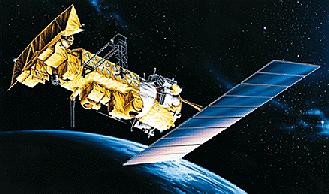
 | NOAA 15 Credit: Manufacturer Image |
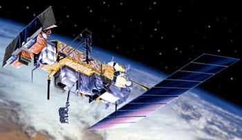 | NOAA 18 Credit: Manufacturer Image |
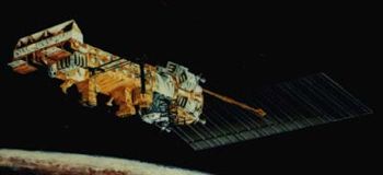
 | NOAA 13 Credit: Manufacturer Image |
 | NOAA 8 Credit: Manufacturer Image |
 | Advanced Tiros N Credit: Lockheed-Martin |
1983 March 28 - . 15:52 GMT - . Launch Site: Vandenberg. Launch Complex: Vandenberg SLC3W. LV Family: Atlas. Launch Vehicle: Atlas E.
- NOAA 8 - . Payload: NOAA E. Mass: 3,775 kg (8,322 lb). Nation: USA. Agency: NOAA. Program: Tiros. Class: Earth. Type: Weather satellite. Spacecraft: Advanced Tiros N. USAF Sat Cat: 13923 . COSPAR: 1983-022A. Apogee: 817 km (507 mi). Perigee: 793 km (492 mi). Inclination: 98.60 deg. Period: 101.00 min. Carried search and rescue package. Spacecraft engaged in practical applications and uses of space technology such as weather or communication (US Cat C). .
1984 December 12 - . 10:42 GMT - . Launch Site: Vandenberg. Launch Complex: Vandenberg SLC3W. LV Family: Atlas. Launch Vehicle: Atlas E.
- NOAA 9 - . Payload: NOAA F. Mass: 1,712 kg (3,774 lb). Nation: USA. Agency: NOAA. Program: Tiros. Class: Earth. Type: Weather satellite. Spacecraft: Advanced Tiros N. USAF Sat Cat: 15427 . COSPAR: 1984-123A. Apogee: 855 km (531 mi). Perigee: 833 km (517 mi). Inclination: 99.10 deg. Period: 101.80 min. Spacecraft engaged in practical applications and uses of space technology such as weather or communication (US Cat C). .
1986 September 17 - . 15:52 GMT - . Launch Site: Vandenberg. Launch Complex: Vandenberg SLC3W. LV Family: Atlas. Launch Vehicle: Atlas E.
- NOAA 10 - . Payload: NOAA G. Mass: 1,700 kg (3,700 lb). Nation: USA. Agency: NOAA. Program: Tiros. Class: Earth. Type: Weather satellite. Spacecraft: Advanced Tiros N. USAF Sat Cat: 16969 . COSPAR: 1986-073A. Apogee: 816 km (507 mi). Perigee: 795 km (493 mi). Inclination: 98.50 deg. Period: 101.00 min. Spacecraft engaged in practical applications and uses of space technology such as weather or communication (US Cat C). .
1988 September 24 - . 10:02 GMT - . Launch Site: Vandenberg. Launch Complex: Vandenberg SLC3W. LV Family: Atlas. Launch Vehicle: Atlas E.
- NOAA 11 - . Payload: NOAA H. Mass: 1,712 kg (3,774 lb). Nation: USA. Agency: NOAA. Program: Tiros. Class: Earth. Type: Weather satellite. Spacecraft: Advanced Tiros N. USAF Sat Cat: 19531 . COSPAR: 1988-089A. Apogee: 854 km (530 mi). Perigee: 838 km (520 mi). Inclination: 99.20 deg. Period: 101.90 min. Carried search & rescue package. Spacecraft engaged in practical applications and uses of space technology such as weather or communication (US Cat C). .
1993 August 9 - . 10:02 GMT - . Launch Site: Vandenberg. Launch Complex: Vandenberg SLC3W. LV Family: Atlas. Launch Vehicle: Atlas E.
- NOAA 13 - . Payload: NOAA I. Mass: 1,712 kg (3,774 lb). Nation: USA. Agency: NOAA. Program: Tiros. Class: Earth. Type: Weather satellite. Spacecraft: Advanced Tiros N. USAF Sat Cat: 22739 . COSPAR: 1993-050A. Apogee: 860 km (530 mi). Perigee: 846 km (525 mi). Inclination: 99.20 deg. Period: 102.00 min. Spacecraft engaged in practical applications and uses of space technology such as weather or communication (US Cat C). .
1994 December 30 - . 10:02 GMT - . Launch Site: Vandenberg. Launch Complex: Vandenberg SLC3W. LV Family: Atlas. Launch Vehicle: Atlas E.
- NOAA 14 - . Payload: NOAA K. Mass: 1,712 kg (3,774 lb). Nation: USA. Agency: NOAA. Program: Tiros. Class: Earth. Type: Weather satellite. Spacecraft: Advanced Tiros N. USAF Sat Cat: 23455 . COSPAR: 1994-089A. Apogee: 861 km (534 mi). Perigee: 847 km (526 mi). Inclination: 98.88 deg. Period: 102.02 min.
1998 May 13 - . 15:52 GMT - . Launch Site: Vandenberg. Launch Complex: Vandenberg SLC4W. LV Family: Titan. Launch Vehicle: Titan II SLV.
- NOAA 15 - .
Payload: NOAA K. Mass: 3,775 kg (8,322 lb). Nation: USA.
Agency: NOAA.
Manufacturer: RCA.
Program: Tiros.
Class: Earth.
Type: Weather satellite. Spacecraft: Advanced Tiros N .
USAF Sat Cat: 25338 . COSPAR: 1998-030A. Apogee: 824 km (512 mi). Perigee: 807 km (501 mi). Inclination: 98.70 deg. Period: 101.20 min.
NOAA K carried a new microwave sensor in addition to the standard optical/near-infrared radiometers and imagers and the SARSAT search and rescue package. It was the first NOAA launch to use the Titan 23G launch vehicle, a refurbished ICBM. Titan 23G-12 placed NOAA K into a suborbital trajectory 6 minutes after launch. A Star 37XFP solid motor on the satellite fired at apogee to put NOAA K in orbit.
2000 September 21 - . 10:22 GMT - . Launch Site: Vandenberg. Launch Complex: Vandenberg SLC4W. LV Family: Titan. Launch Vehicle: Titan II SLV.
- NOAA 16 - .
Payload: NOAA-L. Mass: 1,476 kg (3,254 lb). Nation: USA.
Agency: NOAA.
Manufacturer: Lockheed.
Program: Tiros.
Class: Earth.
Type: Weather satellite. Spacecraft: Advanced Tiros N.
USAF Sat Cat: 26536 . COSPAR: 2000-055A. Apogee: 867 km (539 mi). Perigee: 853 km (530 mi). Inclination: 98.79 deg. Period: 102.06 min.
Launch attempt on September 20 scrubbed. The NOAA polar orbit weather satellite, an Advanced Tiros N with a suite of imaging and sounding instruments. The two-stage Titan II launch vehicle, serial 23G-13, put NOAA-L into a suborbital -2500 x 800 km x 98.0 deg trajectory. The spacecraft's Thiokol Star 37XFP solid motor fired at apogee to circularize the sun-synchronous orbit at 800 km.
2005 May 20 - . 10:22 GMT - . Launch Site: Vandenberg. Launch Complex: Vandenberg SLC2W. LV Family: Thor. Launch Vehicle: Delta 7320-10C.
- NOAA 18 - . Payload: NOAA-N. Mass: 1,420 kg (3,130 lb). Nation: USA. Agency: NOAA. Manufacturer: Lockheed. Program: Tiros. Class: Earth. Type: Weather satellite. Spacecraft: Advanced Tiros N. USAF Sat Cat: 28654 . COSPAR: 2005-018A. Apogee: 866 km (538 mi). Perigee: 847 km (526 mi). Inclination: 98.70 deg. Period: 102.10 min. Delayed from June 30, 2004, February 12, March 10 and 19, May 11, 12, 13 and 14..
2009 February 6 - . 10:22 GMT - . Launch Site: Vandenberg. Launch Complex: Vandenberg SLC2W. LV Family: Thor. Launch Vehicle: Delta 7320-10C.
- NOAA 19 - . Payload: NOAA-O. Mass: 1,420 kg (3,130 lb). Nation: USA. Agency: NOAA. Manufacturer: Lockheed. Program: Tiros. Class: Earth. Type: Weather satellite. Spacecraft: Advanced Tiros N. USAF Sat Cat: 33591 . COSPAR: 2009-005A. Apogee: 867 km (538 mi). Perigee: 845 km (525 mi). Inclination: 98.80 deg. Period: 102.10 min.
Back to top of page
Home - Search - Browse - Alphabetic Index: 0- 1- 2- 3- 4- 5- 6- 7- 8- 9
A- B- C- D- E- F- G- H- I- J- K- L- M- N- O- P- Q- R- S- T- U- V- W- X- Y- Z
© 1997-2019 Mark Wade - Contact
© / Conditions for Use