
Home - Search - Browse - Alphabetic Index: 0- 1- 2- 3- 4- 5- 6- 7- 8- 9
A- B- C- D- E- F- G- H- I- J- K- L- M- N- O- P- Q- R- S- T- U- V- W- X- Y- Z
Mariner 6-7
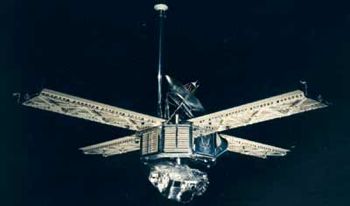
 Mariner 6, 7 Credit: NASA |
Status: Operational 1969. First Launch: 1969-02-25. Last Launch: 1969-03-27. Number: 2 . Gross mass: 412 kg (908 lb). Height: 3.35 m (10.99 ft).
The primary objectives of the missions were to study the surface and atmosphere of Mars during close flybys to establish the basis for future investigations, particularly those relevant to the search for extraterrestrial life, and to demonstrate and develop technologies required for future Mars missions and other long-duration missions far from the Sun. Each spacecraft carried a wide- and narrow-angle television camera, an infrared spectroscope, an infrared radiometer, and an ultraviolet spectroscope.
The spacecraft were oriented entirely to planetary data acquisition, and no data were obtained during the trip to Mars or beyond Mars. Mariners 6 and 7 were designed to fly over the equator and southern hemisphere of Mars. Mariner 6 encountered Mars on July 31,1969 and was quickly followed by Mariner 7 on August 4, 1969. The two spacecraft returned a combined total of 143 approach pictures of the planet and 55 close-up pictures. These images, from the vehicles' television cameras, included pictures of the northern and southern polar caps as well as Phobos, one of Mars' two moons. The spacecraft also studied the Martian atmosphere and profiled its chemical composition. Closest approach to Mars for both spacecraft was approximately 3,550 kilometers. The cost of the two missions was $148 million.
Spacecraft and Subsystems
The Mariner 6 and 7 spacecraft were identical, consisting of an octagonal magnesium frame base, 138.4 cm diagonally and 45.7 cm deep. A conical superstructure mounted on top of the frame held the high-gain 1 meter diameter parabolic antenna and four solar panels, each measuring 215 x 90 cm, were affixed to the top corners of the frame. The tip-to-tip span of the deployed solar panels was 5.79 m. A low-gain omnidirectional antenna was mounted on a 2.23 m high mast next to the high-gain antenna. Underneath the octagonal frame was a two-axis scan platform which held scientific instruments. Overall science instrument mass was 57.6 kg. The total height of the spacecraft was 3.35 m.
The spacecraft was attitude stabilized in three axes (referenced to the sun and the star, Canopus) through the use of 3 gyros, 2 sets of 6 nitrogen jets mounted on the ends of the solar panels, a Canopus tracker, and two primary and four secondary sun sensors. Propulsion was provided by a 223 N rocket motor mounted within the frame which used monopropellant hydrazine. The nozzle with 4-jet vane vector control protruded from one wall of the octagonal structure. Power was supplied by 17,472 photovoltaic cells covering an area of 7.7 square meters on the four solar panels. These could provide 800 W of power near Earth and 449 W at Mars. The maximum power requirement was 380 W at Mars encounter. A 1200 W-hr rechargeable silver-zinc battery was used to provide backup power. Thermal control was achieved through the use of adjustable louvers on the sides of the main compartment.
Three telemetry channels were available for telecommunications. Channel A carried engineering data at 8 1/3 or 33 1/3 bps, channel B carried scientific data at 66 2/3 or 270 bps and channel C carried science data at 16,200 bps. Communications were accomplished via the high- and low-gain antennas via dual S-band traveling wave tube 10/20 W amplifiers for transmission and a single receiver. An analog tape recorder with a capacity of 195 million bits could store television images for subsequent transmission. Other science data was stored on a digital recorder. The command system, consisting of a central computer and sequencer (CC&S), was designed to actuate specific events at precise times. The CC&S was programmed with a standard mission and a conservative backup mission before launch, but could be commanded and reprogrammed in flight. It could perform 53 direct commands, 5 control commands, and 4 quantitative commands.
Payload:
The planetary experiments (59 kg) included two television cameras, an infrared radiometer, an infrared spectrometer, and an ultraviolet spectrometer. These sensors took TV pictures of Mars and measured the ratio of refractivity and UV and IR emissions of the atmosphere.
More at: Mariner 6-7.
Family: Mars flyby. Country: USA. Launch Vehicles: Atlas, Mars tactical rocket, Atlas SLV-3C Centaur. Projects: Mariner, Mars. Launch Sites: Cape Canaveral, Cape Canaveral LC36A, Cape Canaveral LC36B. Agency: JPL, NASA. Bibliography: 2, 278, 296, 3905, 6, 12796.
 | Mariner 6 Credit: Manufacturer Image |
1969 February 25 - . 01:29 GMT - . Launch Site: Cape Canaveral. Launch Complex: Cape Canaveral LC36B. LV Family: Atlas. Launch Vehicle: Atlas SLV-3C Centaur.
- Mariner 6 - .
Payload: Mariner 69-3. Mass: 412 kg (908 lb). Nation: USA.
Agency: JPL,
NASA.
Program: Mariner.
Class: Mars.
Type: Mars probe. Spacecraft Bus: Mariner.
Spacecraft: Mariner 6-7.
USAF Sat Cat: 3759 . COSPAR: 1969-014A.
Mars flyby 31 July 1969; returned 75 images of Martian surface. Ten days before the scheduled launch, a faulty switch opened the main valves on the Atlas stage. This released the pressure which supported the Atlas structure, and as the booster deflated it began to crumple. Two ground crewman started pressurizing pumps, saving the structure from further collapse. The two ground crewman, who had acted at risk of the 12-story rocket collapsing on them, were awarded Exceptional Bravery Medals from NASA.
The Mariner 6 spacecraft was removed, put on another Atlas/Centaur, and launched on schedule. The main booster was jettisoned 4 min. 38 sec. after launch, followed by a 7.5 minute Centaur burn to inject the spacecraft into Mars direct trajectory. After Mariner 6 separated from the Centaur the solar panels were deployed. A midcourse correction involving a 5.35 second burn of the hydrazine rocket occurred on 1 March 1969. A few days later explosive valves were deployed to unlatch the scan platform. Some bright particles released during the explosion distracted the Canopus sensor, and attitude lock was lost temporarily. It was decided to place the spacecraft on inertial guidance for the Mars flyby to prevent a similar occurrence.
On 29 July, 50 hours before closest approach, the scan platform was pointed to Mars and the scientific instruments turned on. Imaging of Mars began 2 hours later. For the next 41 hours, 49 approach images (plus a 50th fractional image) of Mars were taken through the narrow-angle camera. At 05:03 UT on 31 July the near-encounter phase began, including collection of 26 close-up images. Due to a cooling system failure, channel 1 of the IR spectrometer did not cool sufficiently to allow measurements from 6 to 14 micrometers so no infrared data were obtained over this range. Closest approach occurred at 05:19:07 UT at a distance of 3431 km from the martian surface. Eleven minutes later Mariner 6 passed behind Mars and reappeared after 25 minutes. X-band occultation data were taken during the entrance and exit phases. Science and imaging data were played back and transmitted over the next few days. The spacecraft was then returned to cruise mode which included engineering and communications tests, star photography TV tests, and UV scans of the Milky Way and an area containing comet 1969-B. Periodic tracking of the spacecraft in its heliocentric orbit was also done.
Science Results
Mariner 6 returned 49 far encounter and 26 near encounter images of Mars. Close-ups from the near encounter phases covered 20% of the surface. The spacecraft instruments measured UV and IR emissions and radio refractivity of the Martian atmosphere. Images showed the surface of Mars to be very different from that of the Moon, in some contrast to the results from Mariner 4. The south polar cap was identified as being composed predominantly of carbon dioxide. Atmospheric surface pressure was estimated at between 6 and 7 mb. Radio science refined estimates of the mass, radius and shape of Mars.
1969 March 27 - . 22:22 GMT - . Launch Site: Cape Canaveral. Launch Complex: Cape Canaveral LC36A. LV Family: Atlas. Launch Vehicle: Atlas SLV-3C Centaur.
- Mariner 7 - .
Payload: Mariner 69-2. Mass: 412 kg (908 lb). Nation: USA.
Agency: JPL,
NASA.
Program: Mariner.
Class: Mars.
Type: Mars probe. Spacecraft Bus: Mariner.
Spacecraft: Mariner 6-7.
USAF Sat Cat: 3837 . COSPAR: 1969-030A.
Mars flyby 5 August 1969; returned 126 images of Martian surface. Mariner 7 was launched on a direct-ascent trajectory to Mars 31 days after Mariner 6. On 8 April 1969 a midcourse correction was made by firing the hydrazine moter for 7.6 seconds. On 8 May Mariner 7 was put on gyro control to avoid attitude control problems which were affecting Mariner 6. On 31 July telemetry from Mariner 7 was suddenly lost and the spacecraft was commanded to switch to the low-gain antenna. It was later successfully switched back to the high-gain antenna. It was thought that leaking gases, perhaps from the battery which later failed a few days before encounter, had caused the anomaly.
At 09:32:33 GMT on 2 August 1969 Mariner 7 bagan the far-encounter sequence involving imaging of Mars with the narrow angle camera. Over the next 57 hours, ending about 5 hours before closest approach, 93 images of Mars were taken and transmitted. The spacecraft was reprogrammed as a result of analysis of Mariner 6 images. The new sequence called for the spacecraft to go further south than originally planned, take more near-encounter pictures, and collect more scientific data on the lighted side of Mars. Data from the dark side of Mars were to be transmitted directly back to Earth but there would be no room on the digital recorder for backup due to the added dayside data. At closest approach, 05:00:49 GMT on 5 August, Mariner 7 was 3430 km above the martian surface. Over this period, 33 near-encounter images were taken. About 19 minutes after the flyby, the spacecraft went behind Mars and emerged roughly 30 minutes later. X-band occultation data were taken during the entrance and exit phases. Science and imaging data were played back and transmitted over the next few days. The spacecraft was then returned to cruise mode which included engineering and communications tests, star photography TV tests, and UV scans of the Milky Way and an area containing comet 1969-B. Periodic tracking of the spacecraft in its heliocentric orbit was also done.
Science Results
The total data return for Mariners 6 and 7 was 800 million bits. Mariner 7 returned 93 far and 33 near encounter images. Close-ups from the near encounter phases covered 20% of the surface. The spacecraft instruments measured UV and IR emissions and radio refractivity of the Martian atmosphere. Images showed the surface of Mars to be very different from that of the Moon, in some contrast to the results from Mariner 4. The south polar cap was identified as being composed predominantly of carbon dioxide. Atmospheric surface pressure was estimated at between 6 and 7 mb. Radio science refined estimates of the mass, radius and shape of Mars.
1969 July 31 - .
- Mariner 6, Mars Flyby - . Nation: USA. Spacecraft Bus: Mariner. Spacecraft: Mariner 6-7.
1969 July 31 - .
- Mariner 6 fly-by of Mars - .
Nation: USA.
Spacecraft Bus: Mariner.
Spacecraft: Mariner 6-7.
Mariner 6 encountered Mars on July 31,1969. Together with Mariner 7, which arrived four days later, it returned a combined total of 143 approach pictures of the planet and 55 close-up pictures. These images, from the vehicles' television cameras, included pictures of the northern and southern polar caps as well as Phobos, one of Mars' two moons.
1969 August 4 - .
- Mariner 7 fly-by of Mars - .
Nation: USA.
Spacecraft Bus: Mariner.
Spacecraft: Mariner 6-7.
Mariners 6 and 7 were designed to fly over the equator and southern hemisphere of Mars. Mariner 7 encountered Mars on August 4, 1969. The two spacecraft returned a combined total of 143 approach pictures of the planet and 55 close-up pictures. The spacecraft also studied the Martian atmosphere and profiled its chemical composition. Closest approach to Mars for both spacecraft was approximately 3,550 kilometres.
1969 August 5 - .
- Mariner 7 Mars Flyby - . Nation: USA. Spacecraft Bus: Mariner. Spacecraft: Mariner 6-7.
Back to top of page
Home - Search - Browse - Alphabetic Index: 0- 1- 2- 3- 4- 5- 6- 7- 8- 9
A- B- C- D- E- F- G- H- I- J- K- L- M- N- O- P- Q- R- S- T- U- V- W- X- Y- Z
© 1997-2019 Mark Wade - Contact
© / Conditions for Use