
Home - Search - Browse - Alphabetic Index: 0- 1- 2- 3- 4- 5- 6- 7- 8- 9
A- B- C- D- E- F- G- H- I- J- K- L- M- N- O- P- Q- R- S- T- U- V- W- X- Y- Z
RSA-4
 RSA-4 RSA-4 South African space launcher |
Status: Development ended 1994. Payload: 770 kg (1,690 lb). Thrust: 2,000.00 kN (449,600 lbf). Gross mass: 80,000 kg (176,000 lb). Height: 23.50 m (77.00 ft). Diameter: 2.40 m (7.80 ft). Apogee: 400 km (240 mi).
The second and third stages were essentially those of the RSA-3. The fourth stage was clearly adapted from an ICBM MIRV post-boost bus platform. As an ICBM or orbital nuclear system the RSA-4 would have been capable of delivering a single 700 kg warhead anywhere on earth.
Work on the RSA-4 was cancelled in 1994. An attempt was made by Houwteq to market the RSA-4 as a launcher for MEO earth satellite constellations. It was not to be...but the sales brochure from that effort survives and is reproduced below.
Introduction to RSA-4 Launch Vehicle
Houwteq
FOREWARD
The South African Space Industry is spearheaded by Houwteq. Houwteq is the prime contractor in the space industry for space systems and services and is supported by twenty local subcontractors. Most of the subcontractors had established proven capabilities in the high technology field before joining the space industry. Houwteq is the systems house responsible for the space system design, assembly, integration, launch preparation and execution and project management of space activities. The company is located near Grabouw in the Cape Province. Houwteq's subcontractors are responsible for the design, development,, qualification, production, as well as technical and logistic support, at configuration item level.
Houwteq is offering a comprehensive launch service with its RSA-4 Launch Vehicle from the Overberg Test Range situated in South Africa.
Chapter 1
1.1 Purpose of Document
This document is intended as an introduction to the RSA-4 launch vehicle and the launch service offered to prospective clients for placing small to medium sized payloads into low earth orbit (LEO).
The document covers the following aspects;
- the geometry and performance of the RSA-4 launch vehicle
Houwteq offers a comprehensive service for LEO launches including the launch vehicle, the launch facility and associated services.
The RSA-4 launch vehicle comprises three solid propellant boost stages and a hydrazine powered fourth stage for accurate orbit injection and positioning, It can lift a satellite with a mass of 550 kg into a circular orbit at a height of 1400 km and a inclination of 55 degrees.
Provision is made for a payload volume of 10.4 m3 with a maximum diameter of 2.2 m.
II is possible to launch two satellites into different orbits which are in the same orbital plane. The launch vehicle is described in more detail in Chapter 2.
Launches are conducted from the newly established facility at the Overberg Test Range at the southernmost tip of Africa on the south-eastern coast of the western Cape at Lat 34 deg 35 min S and Long 20 deg 19 min E. The facility (OTR), which extends over a total area of 43,000 hectares, is situated close to the villages of Waenhuiskrans and Bredasdorp. Cape Town, one of the major cities in South Africa, is located approximately 200 km from OTR and has a commercial airport capable of handling large airliners. A good quality highway exists between Cape Town and OTR.
A modern air base adjacent to OTR can accommodate all types of aircraft, The use of this facility could be negotiated for specific transport arrangement if required.
Chapter 2
2.1 System Description
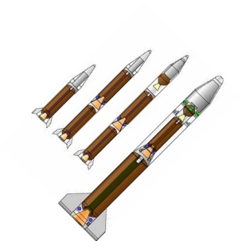
Figure 2.1 shows the overall dimensions and layout of the RSA-4 launch vehicle. It comprises four stages. The first three have solid propellant motors to lift the satellite into orbit. Orbit raising is then performed by means of the fourth hydrazine-propelled stage, which is also used to make fine orbital adjustments to place the satellite accurately into the required orbit. The masses for the stages are respectively 66 metric ton for the first stage, 10 metric ton for the second, 3 metric ton for the third, and approximately 300 kg for the final stage, which gives an all-up mass of 80 metric ton for the complete system. The overall length is 23.5 m with a diameter of 2.4 m.
Provision is made for a payload with a maximum diameter of 2.2 m and a maximum height of 3.74 m. The length of the payload volume at maximum diameter is 1.5 m (Figure 5.4). Two satellites, which fit into the available volume, can be placed into the same orbital plane.
2.2 First Stage
The first stage (Figure 2.2) is propelled by means of a solid propellant motor weighing 62.6 metric ton, of which 58 metric ton is propellant. It delivers an impulse of 139,000 kNs at sea level and burns for 73 s with an average thrust of just under 200 metric ton. The expansion ratio of the carbon-phenolic expansion cone is 14. A graphite throat insert is used. The composite casing is made of Kevlar and covered with cork for thermal insulation. The base and the interstage structures are made of aluminum 2219. Control is done by means of LITVC, as well as air vanes manufactured from honeycomb material. Also situated at the base is a PCM unit for telemetry acquisition and an S-band telemetry transmitter. Power is supplied by 28 volt silver-zinc triggered batteries. In the interstage section on top of the motor is the pyrotechnic activation unit for motor ignition, separation from the launch platform, and detonation of the cutting cords for motor destruction.
2.3 Second Stage
Stage 2 (Figure 2.3) is very similar to stage 1 with following differences:
The motor with 9 metric ton solid propellant burns for 52 s and delivers an impulse of 24,500 kNs with an average thrust of 40 metric ton. Control is done by injecting strontium perchlorate into the motor flame. It is stored in a torus around the nozzle throat and pressurized by means of helium.
The second stage also houses the receivers for destruct in case of malfunction. The destruct channels are redundant and destruct is initiated on receipt of a destruct signal or in case of loss of the carrier wave.
An aluminum aerodynamic sleeve is utilized to provide a constant external diameter between the lower interstage of stage 1 and the avionic section of stage 3. The sleeve is jettisoned after burn-out of stage 1.
2.4 Third Stage
Stage 3 (Figure 2.4) houses the autopilot for digital implementation of the guidance and control algorithms, onboard safety implementation, initiation of discrete events like stage separation, and power switching. Communication is via a 1553 bus. Navigation is performed by a strapdown platform and GPS.
Power is supplied from 28V triggered batteries. Also housed in the third stage is the equipment for tracking and monitoring the launch vehicle, i.e. telemetry, television for monitoring stage separation, a Doppler beacon for measuring velocity and a radar transponder for measuring velocity and range. The structure is made of aluminum. The third stage motor weighs 2 metric ton, with 1,9 metric ton solid propellant in a titanium casing and a nozzle with an expansion ratio of 60. It burns for 92s and delivers a specific impulse of 292 s.
2.5 Fourth Stage
The purpose of the fourth stage (Figure 2.5) is to raise the orbit and to make small orbital adjustments. For this purpose it is equipped with a reactive control system comprising four 50 liter hydrazine tanks, filled to the right level for the particular mission and pressurized by helium, and ten thrusters. Four 200 N thrusters are used for roll control, four 25 N thrusters for pitch and yaw control and two 200 N thrusters for orbit raising. Figure 2.5 shows the layout of the reactive control system.
Navigation is done by means of GPS with a CA code receiver. Rate gyros and accelerometers measure the orientation and velocity increments needed by the control computer for control loop implementation.
The fourth stage provides status information to the satellite during launch on the progression of events, and relays satellite telemetry during launch preparation and launch in the S-band via a stripline antenna to the ground. Power is supplied by 28 V lithium batteries. The structure is made of carbon composite and honeycomb material. The front adapter to the satellite makes provision for cryogenic cooling supply, two electrical connectors for telemetry relay and power supply, as well as for mechanical attachment and pyrotechnic separation of the satellite.
The fairing which protects the satellite is made of a honeycomb composite material and is jettisoned sideways in two halves after stage 2 burn-out.
Chapter 3
3.1 Introduction
The RSA-4 launch vehicle is used to lift small to medium sized satellites into elliptical or circular low earth orbits at inclinations between 37 deg and 90 deg and in sun synchronous. Two satellites can be launched simultaneously, if necessary into different orbits, which must however be in the same orbital plane. Since many different missions are possible, the performance figures and flight profiles are presented for selected cases.
3.2 Lifting Capability
The payload mass which can be placed into a circular orbit for different orbital orbits is given in Figure 3.1 for 55 deg and 90 deg inclinations.
Typical values are
- 550 kg into 1400 km orbit at 55 deg inclination
- 570 kg into 800 km polar orbit.
3.3 Injection Accuracy
The 2-sigma values for the accuracy of injection into a circular orbit are as follows:
- Altitude at injection point : 1 km
- Eccentricity : 0.002
- Inclination : 0.5 deg
- Ascending node : 0.5 deg
As an example of typical values for the main trajectory parameters, their time variation is presented in Figures 3.2 to 3.6 for a 550 kg spacecraft launched at a 55 deg inclination.
3.5 Spacecraft Deployment
In the standard mode the spacecraft will be spun up to >1 rev/s and will be separated with a relative velocity > 0.5 m/s with an angle between the spacecraft longitudinal axis and the velocity vector <5 deg. Requests for other deployment conditions will be handled on an individual basis.
3.6 Launch Sequence
The launch sequence is schematically illustrated in Figure 3.7. The trajectory depends on the particular mission.
As an example the flight parameters and sequence of events are presented for the injection of two satellites into a 1400 km circular orbit.
During the first few seconds after ignition the launcher is rotated from the vertical and flies a gravity turn during the first powered stage. At a height of 40 km, 55 km downrange, the first stage separates, the sleeve is jettisoned, and the second stage motor is ignited. It burns out at a height of 97 km, 230 km downrange, and is jettisoned 25 s later.
Several events are scheduled during the following cruise phase before the third stage motor is ignited. The stage is despun, the satellite protective fairing is jettisoned and then the stage is aligned in the correct orientation for motor firing. Now the stage is spun up and the avionic section separated. At a height of 240 km, 1050 km downrange, the motor is ignited and burns for 92 s. Nutation control is performed during the propelled phase by firing the fourth stage 25 N thrusters intermittently to limit the amplitude of any coning motion which may develop due to thrust or mass asymmetries. The third stage injects the satellite into an elliptical LEO with a perigee of 250 km and burns out 1600 km downrange from the launch site. A period of three minutes is allowed to ensure that the residual thrust drops off to zero before the motor is separated. The satellite plus third stage is now in an elliptical transition orbit with the nominal apogee at the circular orbit height.
Immediately after separation a velocity correction is done if the state vector at burnout deviates from the nominal. The velocity increment required at apogee to circularize the orbit and the time at which it needs to be given is calculated and after half a revolution the thrusters are fired to make the orbit circular. After one revelation the fourth stage, still carrying the two satellites, passes within view of the Overberg ground station. The fourth stage is despun, if required, the two satellites separated pyrotechnically and deployed by means of springs. Half a revolution later when the separation between the fourth stage and the satellites is large enough, the thrusters are fired for the last time to deorbit the stage. If the satellites are given a velocity increment of 0.5 m/s relative to one another and relative to the fourth stage, the two satellites are separated from one another by 5 km along the trajectory and just over 2 km in height after half a revolution and the fourth stage is separated from the satellite nearest to it by the same margin (Figure 3.8). The fourth stage starts off in front of the satellites at separation, but goes into a slightly higher orbit and is in fact overtaken by the satellites.
The remaining problem is to synchronize the phase angle of the satellite in its orbital plane with that of its allocated slot in the constellation. In the launch sequence outlined here, it is assumed that this will he done by the satellite. If the maneuver is done over a few days, it requires little hydrazine. Should it be a requirement, this function could be performed using the fourth stage. In this case the feasibility will be investigated with the client, the limiting factor being the power required by the spacecraft up to deployment.
It will be possible to inject the two spacecraft into different elliptical or circular orbits provided that they are in the same orbital plane and that the energy requirements are within bounds. Provision is made to give a payload of 550 kg a velocity increment of 300 m/s with the fourth stage.
3.7 Launch Execution
If the spacecraft is to be launched into an orbit with a specified nodal angle and if the direction of motion in the orbit is prescribed, then energy considerations and the range safety volume restrict the opportunity for launching to a window of fifteen minutes around a particular time once a day.
It will be possible to monitor the launch from the Overberg ground station up to burnout of the third stage motor. This is the most intensive part of the launch. Separation of the third stage motor and the velocity correction directly afterwards take place after it has disappeared over the horizon During development flight test these events will be monitored from a downrange telemetry station onboard a ship.
Orbit determination necessary for the calculation of the velocity increments needed for orbit raising will be done by the fourth stage using GPS, with the ground station only used for verification. Circularization of the orbit will be performed after half a revolution. It will preferable to involve a ground station in the Northern Hemisphere to monitor this event. The ground stations at Hawaii, Fairbanks and Guam have line-of-sight communication at this point (Figure 3.11).
Figures 3.9 and 3.10 show the ground track of the satellite for a 55 deg inclination. At an orbital height of 1400 km it will pass within view of the Overberg ground station for the first six revolution.
LEO Payload: 770 kg (1,690 lb) to a 400 km orbit at 55.00 degrees. Payload: 550 kg (1,210 lb) to a 1400 km 55 deg orbit.
Stage Data - RSA-4
- Stage 1. 1 x RSA-4-1. Gross Mass: 66,000 kg (145,000 lb). Empty Mass: 8,000 kg (17,600 lb). Thrust (vac): 1,520.000 kN (341,700 lbf). Isp: 270 sec. Burn time: 73 sec. Isp(sl): 244 sec. Diameter: 2.40 m (7.80 ft). Span: 5.90 m (19.30 ft). Length: 10.30 m (33.70 ft). Propellants: Solid. No Engines: 1. Engine: RSA-4-1. Status: Development 1988. Comments: Vacuum specific impulse / thrust estimated. Sea level 139,000 kNs delivered over 73 seconds. Includes 3400 kg mass of fins, interstage and upper-stage constant-diameter fairing ('sleeve') which is jettisoned after first stage burnout.
- Stage 2. 1 x RSA-4-2. Gross Mass: 11,000 kg (24,000 lb). Empty Mass: 2,000 kg (4,400 lb). Thrust (vac): 470.000 kN (105,660 lbf). Isp: 277 sec. Burn time: 52 sec. Diameter: 1.30 m (4.20 ft). Span: 1.30 m (4.20 ft). Length: 6.40 m (20.90 ft). Propellants: Solid. No Engines: 1. Engine: RSA-4-2. Status: Development 1988. Comments: Essentially identical to RSA-3 second stage. Includes 1000 kg upper stage avionic section / spin table, which is jettisoned prior to stage three ignition.
- Stage 3. 1 x RSA-3-3. Gross Mass: 2,048 kg (4,515 lb). Empty Mass: 170 kg (370 lb). Thrust (vac): 58.800 kN (13,219 lbf). Isp: 298 sec. Burn time: 94 sec. Diameter: 1.30 m (4.20 ft). Span: 1.30 m (4.20 ft). Length: 2.60 m (8.50 ft). Propellants: Solid. No Engines: 1. Engine: RSA-3-3. Status: Out of Production. Comments: Data accurate. Source: Missile exhibit and placards, AF Museum, South Africa. ARC/Rafael AUS 51 is identical.
Family: all-solid, orbital launch vehicle. Country: South Africa. Stages: RSA-3-3, RSA-4-1, RSA-4-2. Agency: IAI.
 | Title Page Introduction to the RSA-4 Launch Vehicle Credit: Denel / Houwteq |
 | Figure 2.1 RSA-4 Launch Vehicle Credit: Denel / Houwteq |
 | Figure 2.2 Stage 1 Credit: Denel / Houwteq |
 | Figure 2.3 Stage 2 Credit: Denel / Houwteq |
 | Figure 2.4 Stages 3, 4 and Payload Credit: Denel / Houwteq |
 | Figure 2.5 Stage 4 with Third Stage Motor Credit: Denel / Houwteq |
 | Figure 3.1 RSA 4 Satellite Mass in Circular Orbit Credit: Denel / Houwteq |
 | Figure 3.2 RSA 4 Acceleration During Launch Credit: Denel / Houwteq |
 | Figure 3.3 RSA 4 Velocity During Launch Credit: Denel / Houwteq |
 | Figure 3.4 RSA 4 Ground Range During Launch Credit: Denel / Houwteq |
 | Figure 3.5 RSA 4 Launch Trajectory Credit: Denel / Houwteq |
 | Figure 3.6 Dynamic Pressure During Launch Credit: Denel / Houwteq |
 | Figure 3.7 Launch Sequence Credit: Denel / Houwteq |
 | Figure 3.8 Stage 4 / Satellite Separation in 1400 km Orbit Credit: Denel / Houwteq |
 | Figure 3.9 Satellite Ground Track for 65 deg Inclination Credit: Denel / Houwteq |
 | Figure 3.10 Satellite Ground Track from Polar Perspective for 55 deg Inclination Credit: Denel / Houwteq |
 | Figure 3.11 Ground Station Coverage for Delta-V Burn to Circularise Orbit at 1400 km Credit: Denel / Houwteq |
 | RSA-1 , -2, -3, -4 |
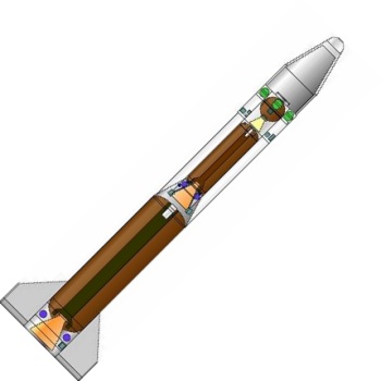
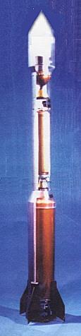 | Model of RSA-4 Model of RSA-4 space launcher, the planned follow-on to the RSA-3. The RSA-4 would have been 23.5 m long and could lift 550 kg into a 1,400-km orbit. This model differs in some details from drawings in the RSA-4 sales brochure. |
Back to top of page
Home - Search - Browse - Alphabetic Index: 0- 1- 2- 3- 4- 5- 6- 7- 8- 9
A- B- C- D- E- F- G- H- I- J- K- L- M- N- O- P- Q- R- S- T- U- V- W- X- Y- Z
© 1997-2019 Mark Wade - Contact
© / Conditions for Use