
Home - Search - Browse - Alphabetic Index: 0- 1- 2- 3- 4- 5- 6- 7- 8- 9
A- B- C- D- E- F- G- H- I- J- K- L- M- N- O- P- Q- R- S- T- U- V- W- X- Y- Z
BIS Lunar Lander
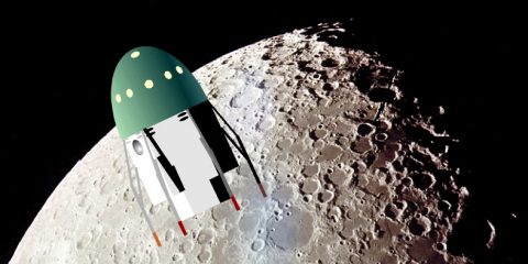
BIS Lunar Lander
BIS Lunar Lander design of 1938
Credit: © Mark Wade
Status: Study 1939. Gross mass: 1,000 kg (2,200 lb).
The purpose of the exercise was to prove that a manned lunar expedition could be designed using existing powder rocket technology. The design was reformulated in 1947 based on information on German advances with liquid propellant rockets.
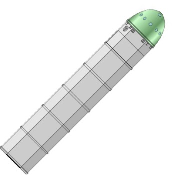
Available British rocket technology then consisting only of powder rockets, the booster consisted of 2,490 such rockets, which were shed as soon as they were exhausted. Thus a kind of 'infinite' staging was used to compensate for the very low specific impulse of the motors. The hexagonal booster was 6 meters in diameter and 32 meters long, with a lift-off mass of 1112 metric tons. Launch was from a flooded caisson in a high-altitude lake near the equator. The one metric ton spacecraft delivered a crew of three to the lunar surface, landing on gear very similar to those used for the Apollo Lunar Module sixty years later. Following re-entry in the earth's atmosphere, a parachute was used for final descent. Oddly, heating during ascent through the atmosphere was seen as a real problem, while re-entry on return was considered trivial ("accomplished in easy stages" via aerobraking). Therefore a jettisonable ceramic shield protected the spacecraft from heating expected to reach 1500 deg C during ascent, while no heat shield was considered necessary for return.
J Happian Edwards led the design team, which included H Bramhill (draftsman), Arthur C Clarke (astronomer), A V Cleaver (aircraft engineer), M K Hanson (mathematician), Arthur Hanser (chemist), S Klemantski (biologist), HE Ross (electrical engineer), and R A Smith (turbine engineer).
Here is the original introduction to the article, as written by H E Ross.
The BIS spaceship design is such a radical departure from all previously conceived ideas of a spaceship that a full explanation is called forIn designing a spaceship the designer has a completely different problem to that involved in the design of any other means of transport. A motor car, railway train, airplane or ship consists basically of a vessel and a fuel tank, in the latter being placed the fuel required for a journey or journeys. The shortest spaceship voyage, however, is the journey to the Moon, and with the most optimistic estimates of the fuel energy and motor efficiency the quantity of fuel required will still be such that the fuel tank would require to be much larger than the rest of the ship. Consequently we must revert to the old system of petrol cans, so designing our ship that the cans can be attached outside the ship and thrown away when empty. The last condition does not mean that the cans are cheap --- they are actually precision engineering jobs, and horribly expensive --- but the cost of the fuel needed to bring them back would be even greater. We find by careful calculation that with the best fuels and motors that we can afford it will require about 1000 metric tons of fuel to take a 1 metric ton vessel to the Moon and back, so our problem has been to design a 1 metric ton spaceship with containers for 1000 metric tons of fuel attached outside and detachable.
The nature of rocket motors has also affected the design considerably. With such motors as aero-engines a larger unit can be made lighter in proportion to its power than a small unit, but in the case of rocket motors quite the reverse is the case; in fact the proportionate weight of rocket motors rises so steeply that a motor of more than about 100,000 hp is hardly feasible, and as the lifting of the 1000 metric tons at the start calls for many millions of h.p. this requires a considerable number of small units. Again, since the cost of the motors is less than the cost of the fuel required to bring them back, and as only a few small motors will be required to land the 1 metric ton ship on its return against over a hundred large ones at the start, the motors are jettisoned after use.
For a maximum fuel economy, anything which is to be jettisoned should be jettisoned as soon as possible, and this has led to the cellular spaceship design, with hundreds of small units each comprising a motor and its fuel tank, and each so attached that as soon as it ceases to thrust it falls off. This early detachment of all dead weight has resulted in an enormous increase of efficiency over earlier designs, and has reduced the fuel required for a return voyage to the Moon from millions of metric tons to thousands of metric tons.
Owing to the large number of small units, it is possible to start a motor and run it till its load of fuel is exhausted, controlling both thrust and direction by the rate at which fresh tubes are fired. This makes it possible to use solid fuel for the main thrust, with consequent considerable saving in weight, and giving the additional advantages that the strength of the fuel helps to support the parts above and its high density makes the ship very compact. Liquid fuel motors are, however, provided for stages requiring fine control, and also steam jet motors for steering.
The approximately hemispherical portion of the vessel (to the downward pointing cone) is the life container. The portion between the two cones contains the air-lock, air-conditioning plant, heavy stores, batteries and liquid fuel and steam jet motors, etc. Below this are the solid fuel tubes for the return voyage. The whole of the remainder of the vessel consists of the tubes for the outward voyage, which have to be jettisoned by the time of arrival at the Moon.
It will be seen that the streamlining is conspicuous by its absence. The form of the ship has been largely dictated by other considerations, and as compared to the terrific power needed to lift the vessel out of the Earth's gravitational field the total air resistance is quite negligible (less than 1%), this does not matter greatly. The diameter of the front of the ship is determined as being the smallest reasonable size for the life container. (It should be noted that this design is for a very small spaceship, about the overall size of a large barge. On larger ships this restriction will be somewhat modified.) The diameter of the rear of the ship is determined by the firing area required. Too small an area calls for excessive pressures in the motors, and consequently excessively heavy construction. The two diameters being approximately the same has led to the straight-sided form. An increase in central diameter would mean improved streamlining, but this would only decrease the resistance below the velocity of sound, and this is only a small proportion of the whole. On the other hand, the straight-sided form gives the greatest strength, which is of major importance, and also serves to minimize frictional heating. The main body of the spaceship, comprising the motor tubes, is hexagonal in shape; this form giving the closest possible stacking of the tubes.
The form of the nose is intended not so much to reduce the resistance at low velocities, as to split the air at high velocities (several times the velocity of sound), so as to maintain a partial vacuum along the sides. The frontal paraboloid portion is a reinforced ceramic carapace, capable of withstanding a temperature of 1500 deg C. in air, and by its form the frictional heating is made a maximum on this portion and minimized on the sides. The carapace (which, of course, has no portholes) is detached once the vessel has got away from the Earth.
The tubes are stacked in conical layers for greater structural stability, since, apart from the vessel proper-the top portion-the whole strength lies in the tubes, and these are not rigidly fixed together, but simply stacked and held in position by one-way bolts and light webs.
The firing order of the tubes is in rings starting from outside and progressing inwards towards the center. While the motors are firing their thrust holds them in place; when expended, the acceleration of the ship causes them to release from position and they drop off. Those in the inner rings of the hank not yet used do not position themselves for release until their firing thrust carries them a fractional distance up the release bolts. A light metal sheath embraces the outermost ring of tubes; this and the webs are discarded when the whole of the previous bank of motors has been jettisoned.
Adjacent to the top of the liquid fuel motors (used for fine control on the lunar landing) are . Tangential tubes. These are necessary to provide the crew with artificial gravitation, which is achieved by rotating the ship (approximately I revolution in 3½ sec). The g value desired is therefore under control of the crew. Not only is this artificial gravitation considered a necessary precaution (the physical effect of long periods of no gravitation being at present unknown), but in any case haphazard rotation of the vessel would almost certainly take place, making navigational observations impossible. Hence control of rotation is essential. Again, before the Moon landing can be attempted, it is necessary to stop rotation in order to prevent disaster to the ship when it touches ground.
It is not anticipated that the spaceship can be so accurately maneuvered that its landing will be without shock. Hydraulic shock absorber arms are therefore incorporated. These are normally collapsed within the hull and are extended just prior to landing.
The firing of the motor tubes is carried out by an automatic electrical selector system, but manual control is used for navigational corrections. The ship, being in rotation, is kept thrusting in the correct direction, but this does not prevent "wobble" if firing is not equal on all sides. Manual control of stability is maintained during the first few seconds of ascent, and after that a pendulum contactor automatically controls stability. The main wiring cable to the tubes is led down a central column, provided at each bank level with a plug connection which breaks away when its purpose has been served and is then jettisoned.
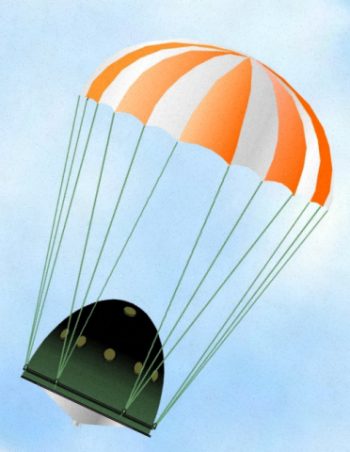
The hemispherical front of the life-compartment is of very light nature, this being made possible on account of the protective carapace above. The segmented carapace is, of course, discarded after passing out of Earth's atmosphere, and protection of the life-compartment shell is not needed for the ascent from Moon. The return into Earth's atmosphere will be done at low velocities, hence heating of this shell will not be excessive. (A parachute is used for final landing).
Owing to the small scale of the diagrams it has not been possible to show many of the fitments and accessories within the life-compartment, but (these include) seats for the crew of three. The controls for firing are placed on the arms of the chairs, and the chairs themselves move on rails round the life-compartment. The crew recline on these chairs with their heads towards the center of the ship and a circular catwalk is provided for them round the circumference of the chamber.
For observation purposes ports are provided in the dome of the life-compartment. Under the flange of the carapace, in the rim of the floor of the life-compartment, are the back-viewing ports; these are covered during thrusting periods. Three forward-viewing ports in the top of the life-compartment shell are also provided. It should be noted that observation of direction cannot be made during the initial thrusting period in ascent from Earth-it being impossible to see backwards through the tail-blast of the ship-the carapace prevents vision in other directions, and in any case the period is too short to allow of stellar observations. Therefore navigation during this period must be done entirely by means of internal instruments which consist of an altimeter, speedometer and accelerometer. Another essential is, of course, a chronometer, and a gyroscope ensures maintenance of direction. A suspended pendulum provides indication of "wobble" and modified sextants and range finders are used to determine position. These instruments are placed in convenient juxtaposition to the crew. The cylindrical objects shown just above the catwalk, against the ports, are coelostats These are synchronized, motor-driven mirror devices something similar to a stroboscope, and it is by means of these that a stationary view of the heavens is provided for navigational observations while the ship is in rotation. The girder structure in the center of the life-compartment is a support for the light shell and also serves to carry navigation instruments. Beneath the carapace were the spidered outer and inner doors of the air-locks.
A launching device for this ship is necessary on its take-off from Earth, but, being accessory to the ship and somewhat complicated, this will be discussed in a subsequent issue of the Journal.
Crew Size: 3.
Family: Lunar Landers, Moon. Country: UK. Agency: BIS. Bibliography: 16.
 | BIS Lunar Lander Credit: © Mark Wade |
 | BIS Lunar Lander Credit: © Mark Wade |
 | BIS Lunar Lander Credit: © Mark Wade |
 | BIS Lunar Lander Credit: © Mark Wade |
1948 November 13 - .
- British Interplanetary Society manned lunar landing mission - .
Nation: UK.
Spacecraft: BIS Lunar Lander.
A paper read to the British Interplanetary Society by H. E. Ross described a manned lunar landing mission which would require a combination of the earth orbit and lunar orbit rendezvous techniques. Three spacecraft would be launched simultaneously into earth orbit, each carrying a pilot. After rendezvous, the crew would transfer to ship A, which would refuel from ships B and C. Ship C would be discarded completely, but ship B would be fueled with the surplus not needed by A. The spacecraft would then be fired into a translunar trajectory. Upon reaching the vicinity of the moon, the spacecraft would go into lunar orbit, detach fuel tanks, and descend to the lunar surface. To return to earth, the spacecraft would rendezvous with the fuel tanks, refuel, and fire into a transearth trajectory. On approaching the earth, the spacecraft would rendezvous with ship B, the crew would transfer to ship B, and descend to earth. The ability to rendezvous in space was seen to be the essential element of such a project. The total payload weight at launch would be 1,326 tons equally divided among the three ships as compared to 2.6 times this weight required for a direct ascent and return from the moon.
Back to top of page
Home - Search - Browse - Alphabetic Index: 0- 1- 2- 3- 4- 5- 6- 7- 8- 9
A- B- C- D- E- F- G- H- I- J- K- L- M- N- O- P- Q- R- S- T- U- V- W- X- Y- Z
© 1997-2019 Mark Wade - Contact
© / Conditions for Use