
Home - Search - Browse - Alphabetic Index: 0- 1- 2- 3- 4- 5- 6- 7- 8- 9
A- B- C- D- E- F- G- H- I- J- K- L- M- N- O- P- Q- R- S- T- U- V- W- X- Y- Z
STCAEM NEP
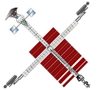 STCAEM NEP Credit: © Mark Wade |
Status: Study 1991. Specific impulse: 10,000 s.
The STCAEM Nuclear Electric Propulsion (NEP) Mars transfer concept offered advantages of a reusable, extremely high Specific Impulse (Isp = 10,000 sec) system; a fully propulsive capture at Mars and Earth which avoided the need for high energy aerobraking; great mission flexibility (relative insensitivity to mission opportunity, capture orbit astrodynamics, or changes in payload mass); and low resupply mass (the argon propellant amounted to roughly a third of total vehicle mass). Disadvantages of the concept were its high technology development cost with a complex, high-performance power system and large, liquid-metal radiator system.
STCAEM (Space Transfer Concepts and Analyses for Exploration Missions) was a major NASA funded study produced by Boeing in 1991. It provided an exhaustive trade analysis of mission profiles and trajectories for manned Mars missions using four different propulsion technologies (cryogenic chemical with aerobraking, nuclear thermal, nuclear electric, and solar electric). Within each study alternate mission profiles using split/sprint missions, flyby rendezvous, and additional aerobraking were examined. Only the baseline for the nuclear electric mission is presented here.
Nominal Mission Outline
- The NEP vehicle was assembled and checked out in LEO
- TMI was a slow spiral out of Earth's gravity well
- Just prior to Earth escape, the crew transferred to the NEP via an LTV
- Thrust continued throughout the interplanetary transfer, first accelerating relative to Earth and then decelerating relative to Mars, except for a 45 - 60 day no-thrust period mid-route.
- MTV would fly by Mars with low relative encounter velocity
- MEV separated from MTV for aeroentry
- MEV descended to surface, jettisoning aerobrake prior to landing
- Surface operations ensue
- MTV continued decelerating into loosely captured, highly elliptical orbit
- Ascent vehicle would leave descent stage and surface payload on surface
- MAV rendezvous occurred at MTV periapsis; berthing and crew transfer
- MAV jettisoned in Mars orbit
- Reversal of interplanetary acceleration / coast / deceleration sequence
- Crew departed MTV for direct entry at Earth
- MTV spiraled back to LEO for refurbishment (optional loose capture at L2 was attractive, if refurbishment infrastructure was available and if resupply trips from LEO used EP or beamed power propulsion for high efficiency)
Primary vehicle systems were: power plant at the bow; radiators amidships; main propulsion astern; vehicle bus; and crew systems near the stern.
Power Plant
The power plant consisted of reactors, shadow shields, boiler (heat exchanger), electromagnetic pumps, and turbo-alternators. Two fast-spectrum (UN-W/25Re) reactors were used for redundancy. The reactors were positioned in line with the main vehicle axis to maximize mutual shielding of the rest of the vehicle. A radiation shield (WBe2C / B4C composite) was required aft of the reactors to protect the crew and sensitive electronic equipment from direct and scattered neutron and gamma fluxes. The shield was shaped to produce a shadow-cone with rectangular cross-section, tailored to the reactors' view of the rest of the vehicle. Lithium was the primary coolant, pumped by redundant electromagnetic pumps through the boiler. The secondary, potassium loop, also pumped electromagnetically, carried heat from the boiler to the turbo-alternator assembly.
There were 5 pairs of turbo-alternators (3 primary and 2 backup pairs), which generated 40 MWe for propulsion. Each turbo-alternator pair counter-rotated to cancel its gyroscopic acceleration. This machinery was configured to permit straightforward robotic maintenance access when the reactors were not running, but the entire turbo-machinery assembly could be launched as one unit in a 10 m launch shroud, already integrated with the pumps, boiler and dormant reactors. The potassium ran through the condenser pipes, which formed the vehicle spine along the length of the radiator system. Reduced-diameter, armored pipes returned the low-quality two phase (mostly liquid) potassium to the boiler to complete the loop.
Radiators
The radiator system consisted of a primary assembly, an alternator assembly and an auxiliary assembly. A typical assembly consisted of several hundred individual, identical, sodium-containing, carbon/carbon heat pipes, whose evaporator ends were bonded mechanically to the secondary-loop condenser pipe. Their radiator fins were oriented in the plane of the overall array, and were bonded mechanically together for overall structural stiffness. The primary assembly cooled the secondary-loop potassium; the alternator assembly cooled the dynamic power conversion system (turbo-alternators); the auxiliary assembly provided cooling to the electromagnetic pumps during normal operations, as well as to the reactors during shutdown.
Propulsion
The propulsion system included engine assembly, propellant storage subsystem, and plumbing. The engine assembly had 40 individual ion thrusters (including 10 spares) in a 5 x 8 rectangular array. Each thruster was 1 m wide by 5 m long; beam neutralizers were located between the thrusters. The argon propellant was stored cryogenically in insulated, spherical tanks, mounted on the forward side of the engine assembly via structural and fluid quick-disconnects. Including tanks, the propellant storage system mass was 185 t (about 35% overall vehicle IMLEO). This low propellant mass was a strong resupply advantage.
Vehicle bus
Thrust loads were extremely low for the EP system. Probable maximum loading was from impulses such as Attitude Control System (ACS) firings, berthing operations, and construction and maintenance activity. The primary vehicle structure was the armored, liquid-metal-carrying condenser pipes of the conversion and radiator systems. Additional lightweight, out-of-plane stiffening structure was provided for the large, fiat radiator panels. Astern of the radiators, an SSF-type truss continued the vehicle spine. The crew systems were attached to this, and the power feeds for the engines were deployed within it. Two communications satellites were embedded in the truss near the crew systems, to be deployed in Mars orbit for maintaining communication with Earth. Also mounted to the truss were deployable solar arrays which provided habitat and vehicle power when the nuclear power system was shut down (during LEO operations and interplanetary coast).
Crew systems
The crew systems consisted of a long-duration transit habitat and one or more MEVs. All habitable volumes were contiguous throughout each mission. The crew systems were wrapped around and hung on the vehicle bus, as far from the nuclear sources as practical without propulsion interference. The separation exceeded 100 m. Electric propulsion had the least sensitivity to increased payload mass, so an important option was provision for multiple MEVs. A multiple docking adapter would allow several MEVs to be used without altering the vehicle configuration (additional propellant tanks would be required).
Nuclear Electric Propulsion Description
This system created electrical power necessary for the propulsion system with a nuclear reactor power system. Thrust was obtained as a result of charged particles accelerated through an electric field. Argon propellant was first ionized in the thruster discharge chamber. The propellant, which was in a plasma state, was contained within the discharge chamber by a magnetic field. The propellant then "drifted" towards the accelerating grid where the charged particles were repelled out at an extremely high velocity. The charged particles had then to be neutralized to prevent them from coming back to the spacecraft, which would negate thrust. An issue confronting the propulsion system involved the expected lifetime of the thrusters due to cathode and grid erosion. Expected thruster lifetime was 10,000-20,000 hrs.
The reactor power system was composed of twin uranium fast reactors. The reactors heated a working fluid which was used to drive turboalternators. The expansion of the working fluid drove the alternators, producing electricity. The working fluid had then to be cooled for reuse through a radiator subsystem. The electrical power was then conditioned for transmission and sent to the thruster system on the distribution bus. Expected power plant lifetime was 10 years. Disposal locations of the spent reactors was a problem with a solution to be determined.
Mission analysis for various vehicles revealed that high power levels (20-40 MWe) coupled with low vehicle specific mass (alpha= 4-7 kg/kW) offered fast trips and low associated IMLEO (400-600 t) for most mission opportunities. Alpha was defined as the specific mass of the vehicle and had the units of kg/kW. Since a vehicle's alpha played such an important role in its performance, technology, areas associated with this aspect of electric propulsion had to be given serious attention early in the development program.
Certain gravity assists offered significant benefits for electric propulsion, without imposing launch window restrictions. The gravity assists that offered benefits were a Lunar fly-by, a Mars fly-by, and an Earth fly-by. During Earth escape, the vehicle would swing by the moon to gain a velocity boost on the order of 600-1000 m/s.
During a Mars fly-by, the vehicle would approach Mars with excess velocity, drop the MEV off, and continue in heliocentric space in close proximity to Mars. When the vehicle decelerated enough to capture at Mars, the vehicle would enter a highly elliptic orbit to allow the MEV multiple attempts to rendezvous with the transfer vehicle. The time frame for vehicle deceleration and Mars capture was calculated to be the same as the surface stay time.
An Earth fly-by would be similar to a Mars fly-by in the sense that the vehicle started the deceleration phase of the mission leg, later than it normally would. As the transfer vehicle approaches the Earth with excess velocity, the crew would be dropped off and the vehicle continue in heliocentric space.
When an Earth fly-by was employed, the transfer vehicle cannot rendezvous back with the Earth for a considerable length of time (-200 days). This length, of time could be detrimental to thruster lifetime. Therefore, the recommended gravity assists were only for Lunar and Mars fly-bys. These fly-bys could offer trip time reductions on the order of 40 days total.
A major operational issue confronting the NEP was departure and refurbishment orbits. Due to differential nodal regression, severe debris environments, and Van Allen belt radiation, the NEP was forced to operate from LEO (400 km) or GEO (35,000 km) and higher. A LEO operational node would offer the greatest advantages for the NEP, if nuclear safety operational issues could be resolved. Preliminary analysis indicated that a multi-megawatt vehicle could operate safely in LEO. Electric propulsion, unlike ballistic trajectories, spiral in and out of Earth Orbit in a circular path. This type of circular spiral eliminates the risk of accidental Earth atmosphere re-entry.
STCAEM NEP Mass Breakdown
Payload
- Descent aerobrake: 7.0 metric tons
- MEV Descent stage: 18.7 metric tons
- MEV ascent stage: 22.5 metric tons
- Surface equipment: 25.0 metric tons
- Transit hab module: 44.1 metric tons
Propulsion
- Reactor 1: 7.4 metric tons
- Reactor 2: 7.4 metric tons
- Shield: 8.6 metric tons
- Primary heat transport system: 20.1 metric tons
- Auxiliary cooling subsystem: 2.2 metric tons
- Boiler: 21.6 metric tons
- Turbo alternators: 16.3 metric tons
- Alternate radiator: 2.6 metric tons
- Turbopumps: 0.4 metric tons
- Rotary fluid management device: 3.1 metric tons
- Main cycle radiator: 10.6 metric tons
- Main cycle condenser: 1.3 metric tons
- Main cycle plumbing: 5.0 metric tons
- Auxiliary cycle radiator: 0.5 metric tons
- Auxiliary cycle condenser: 1.3 metric tons
- Auxiliary cycle plumbing: 6.0 metric tons
- Power conditioning radiator: 1.1 metric tons
- Plumbing insulation: 4.1 metric tons
- Engine assembly: 23.5 metric tons
- Power management and distribution: 68.0 metric tons
Structure
- 5 meter bay graphite epoxy truss: 4.5 metric tons
- Pressurized berthing adapter: 6.6 metric tons
Utilities
- Communications: 0.6 metric tons
- Attitude control: 5.7 metric tons
- Avionics: 2.5 metric tons
- Housekeeping power distribution: 0.5 metric tons
- FV/RFC power subsystem: 2.3 metric tons
- Robotics: 3.6 metric tons
Propellant system
- Tanks: 3.3 metric tons
- Feed lines: 0.1 metric tons
- Propellant: 167.2 metric tons
Subtotal
- 15% Growth: 35.6 metric tons
Mass to resupply after first use: 339.2 metric tons
Power System Summary
- Electrical power: 40 MWe
- Reactor power: 200 MWt
- Type of reactor fuel: UN-W/25Re Cerment
- Peak fuel burn up: 0.25
- Reactor coolant: Lithium
- Reactor outlet temperature: 1550 K
- Turbine inlet temperature: 1450 K
- Main cycle heat rejection temperature: 1000 to 1025 K
- Auxiliary cooling loop heat rejection temperature: 650K
- Power conditioning heat rejection temperature: 400K
- Alternator cooling heat rejection temperature: 440K
- Type of radiators: Heat Pipe
- Power conversion system - 10 years: 3 active/2 backup
STCAEM NEP Mission Summary:
Family: Mars Expeditions. Country: USA. Spacecraft: STCAEM MEV. Propellants: Electric/Xenon. Agency: NASA, Boeing. Bibliography: 1985, 4420.
 | STCAEM NEP Credit: NASA |
 | STCAEM MEP Credit: NASA |
Back to top of page
Home - Search - Browse - Alphabetic Index: 0- 1- 2- 3- 4- 5- 6- 7- 8- 9
A- B- C- D- E- F- G- H- I- J- K- L- M- N- O- P- Q- R- S- T- U- V- W- X- Y- Z
© 1997-2019 Mark Wade - Contact
© / Conditions for Use