
Home - Search - Browse - Alphabetic Index: 0- 1- 2- 3- 4- 5- 6- 7- 8- 9
A- B- C- D- E- F- G- H- I- J- K- L- M- N- O- P- Q- R- S- T- U- V- W- X- Y- Z
Skylon
Skylon
Credit: Adrian Mann
Status: Cancelled 1995. Payload: 12,000 kg (26,000 lb). Thrust: 1,300.00 kN (292,200 lbf). Gross mass: 275,000 kg (606,000 lb). Unfuelled mass: 54,319 kg (119,752 lb). Specific impulse: 425 s. Specific impulse sea level: 2,000 s. Burn time: 1,200 s. Height: 82.00 m (269.00 ft). Diameter: 6.25 m (20.50 ft). Span: 25.00 m (82.00 ft). Apogee: 300 km (180 mi).
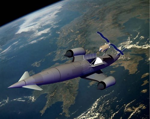
Skylon was an aircraft-like vehicle 82m long with a delta wing mounted mid fuselage carrying wing tip mounted engines. A swept all-moving aft fin provided yaw control, a delta foreplane (canards) provided pitch control and wing trailing edge ailerons provided roll control for atmospheric flight. Reaction thrusters provided control in space.
The vehicle would take off and land using a relatively conventional retractable undercarriage. The fuselage was 6.25m in diameter and the span over the engine nacelles was 25m. At the start of the take-off roll the vehicle weighed 275 metric tons; maximum landing weight was 55 metric tons. The vehicle could deliver 12 metric tons to a 300 km equatorial orbit, 10.5 metric tons to a 460 km equatorial space station or 9.5 metric tons to a 460 km x 28.5 deg space station when operating from an equatorial site.
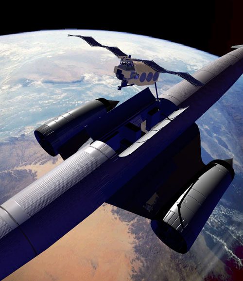
Skylon employed two Sabre hybrid airbreathing/rocket engines. These engines employed liquid hydrogen fuel with atmospheric air up to Mach 5.5 and on-board liquid oxygen beyond that to orbital velocities. At take-off the vehicle carried approximately 66 metric tons of liquid hydrogen and approximately 150 metric tons of liquid oxygen for the ascent.
The fuselage and wing load bearing structure was made from carbon fiber reinforced plastic and consisted of stringers, frames, ribs and spars built as warren girder structures. The aluminum propellant tankage was suspended within this, free to move under thermal and pressurization displacements. The external shell (the aeroshell) was made from a fiber reinforced ceramic and carried only aerodynamic pressure loads which were transmitted to the fuselage structure through flexible suspension points. This shell was thin (0.5mm) and corrugated for stiffness. It was free to move under thermal expansion during the latter stages of the aerodynamic ascent and re-entry.
The Sabre engines were essentially closed cycle rocket engines with an additional precooled turbo-compressor to provide a high pressure air supply to the combustion chamber. During the ascent the engines operated in airbreathing mode up to Mach 5.5 and then as pure rocket engines. Air collection was via a simple conical two shock inlet with a translating center body to maintain shock-on-lip conditions. The center body moved forward to close the inlet for re-entry. A bypass system was used to match the variable captured air flow to the engine demand. This bypass flow was reheated in order to recover the momentum lost through the capture shock system.
The thrust during airbreathing ascent was variable but around 200 metric tons. During rocket ascent this rose to 300 metric tons but was then throttled down towards the end of the ascent to limit the longitudinal acceleration to 3.0g.
The Skylon payload bay was 4.6m diameter and 12.3m long. It was designed to be compatible with expendable launcher payloads but in addition to accept standard aero transport containers which were 8 foot square in cross section and 10, 20, 30 or 40 feet long. It was anticipated that cargo containerization would be an important step forward in space transport operations, enabling the 'clean' payload bay to be dispensed with.
The ground handling operations would be carried out using a standard aircraft tractor and a bonded goods cargo building permitting overhead loading and protection from the elements. For safety and operational simplicity the cryogenic propellants were loaded subcooled without venting of vapor. Cryogen loading was automatic through services connecting in the undercarriage wells while the vehicle was stood on the fuelling apron.
Although essentially a cargo carrier the payload bay could accommodate tankage for propellant supply to orbit based operations, upper stages for orbit transfer operations and, once endurance certification was achieved, a cabin module for 60 passengers.
While on orbit the main propellant tanks were vented and allowed to warm to ambient conditions. Propulsion and attitude control were provided by the OMS/RCS system. This used a common LH2/LO2 propellant storage which was heavily insulated and cryogenically cooled. This system could remain operational on orbit up to 7 days. The Reaction Control System employed gaseous propellants supplied by the Gaseous Propellant Supply System. The GPSS also supplied reactants to the fuel cells and the APU turbines. The Skylon vehicle provided no payload support, being purely a transport system.
During re-entry, which occurred at an altitude between 90 to 60 km, the heat was radiated away from the hot aeroshell. Heat was prevented from entering the vehicle by layers of reflecting foil and the low conductivity shell support posts. Liquid hydrogen was evaporated in the main tanks, passed through thermal screens to intercept the small residual heat leak and then vented overboard.
The Sabre engines were mounted in axisymmetric nacelles on the wingtips. Control authority while in the atmosphere was exerted by foreplanes in pitch, ailerons in roll and an aft mounted fin in yaw. During the ascent main engine gimballing takes over progressively as the dynamic pressure reduced until finally handing over to reaction control thrusters at main engine cutoff. The vehicle was capable of taking off and landing from conventional runways on its own undercarriage. The Skylon configuration evolved from design review of the HOTOL airframe and represented an efficient resolution of the problems encountered by that project.
The aeroshell formed the outer surface of the airplane and therefore had to withstand the local aerodynamic pressure loads and kinetic heating. The aeroshell was passively radiation cooled and during the ascent rose to a maximum of 855K at the bottom of the dive. During reentry the temperature was kept down to 1100K by dynamically controlling the trajectory via active feedback of measured skin temperatures. This was possible by virtue of the low ballistic coefficient and controllability of a lifting vehicle with active foreplanes. The aeroshell was airtight to prevent reentry gases leaking into and destroying the vehicle interior.
The fuselage could be regarded as a beam subject to aerodynamic and inertia loads along its length. The highest loads were in the vertical pitch plane (notably during the 2g pull-up maneuver), however significant lateral loads existed due to the aft fin and during yawed flight, while torsional moments were generated by the fin and the nose wheel. In addition the aerodynamic crossflow component due to the vehicle incidence attempts to distort the fuselage cross section out of round. An unusual design difficulty, unique to spaceplanes, was that during reentry a temperature difference of over 1000deg existed over the radial gap between the tankage and the outer fuselage surface.
The best structural option was to introduce a separate tailored structure running down the length of the fuselage from which the tankage and the aeroshell were suspended. In reviewing the C1 structure it was realized that the novel fuselage insulation system had created an ambient radial air gap outside the tankage into which a cylindrical fuselage girder could be inserted. This enabled the tank pressure to be reduced to the minimum governed by boost pump limits, and the aeroshell to be designed to carry the local pressure loading only.
This type of structure had to be capable of handling compressive loads over considerable distances without buckling. Since the vehicle had a relatively low area loading (due to the hydrogen fuel and 2g stressing limit) and the fuselage resembled a relatively deep beam, a very small amount of material was sufficient to support the loading. Therefore to satisfy elastic stability criteria while retaining high stress levels, the cylindrical girder had to be locally condensed into small stable sections, frequently supported to satisfy global stability (i.e.: a spaceframe ). The spaceframe was composed of ring frames (which supported the aeroshell on radial posts) spaced at 0.3m intervals by shear diagonals. Four main longerons (roughly at the 45 degree points to maximize the section depth) carried the overall fuselage bending moment while avoiding cutouts and sudden changes in slope. The upper longerons formed the payload bay door sill while the lower longerons crested the wing carry through in order to avoid a cutout for main undercarriage stowage.
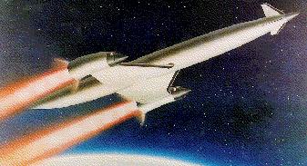
The Sabre engine was designed to deliver a high airbreathing thrust/weight ratio with moderate Specific Fuel Consumption SFC while reverting to a high specific impulse rocket engine at transition. Since the airbreathing mode operates on a turbomachinery based cycle the engine was capable of generating static thrust (unlike ramjet cycles) and engine development could therefore take place on open testbed facilities. Optimum transition from airbreathing to rocket mode with this type of powerplant occurred at around Mach 5 and 26 km, after which the vehicle climbed steeply out of the atmosphere to minimize drag losses. The resulting ascent trajectory was relatively benign to both engine and airframe, leaving a reasonable choice of airframe materials capable of withstanding the ascent and reentry temperatures without active cooling. The Sabre engine was designed with state of the art technology for turbomachinery, pumps and combustion chambers.
By employing the rocket combustion chamber, nozzle and pumps in both modes the mass penalty of adding a separate airbreathing engine was reduced, while also eliminating the base drag penalty of the 'dead' rocket engine during airbreathing ascent..
Extant or near term materials were adopted for the Sabre/Skylon design in order to minimize development risk, placing emphasis on advanced manufacturing techniques and novel structural concepts to achieve lightweight designs. This was what separated the Skylon design from other proposed future transport system designs whose success relied heavily on the use of advanced super-lightweight materials with an unproven track record. Using conventional technologies and materials in a clever way was a far less risk y approach to take. This made the Skylon approach much more commercially sound.
Skylon was designed as a practical utilitarian machine for use by competitive commercial operators. This was seen as the most effective way to ensure that space transportation assumed its proper place in the economy and its continued improvement under 'customer control'. This had dictated a configuration as close to a conventional aircraft as technology would permit. In particular a rolling take-off was seen as essential and by special attention to the brake system it proved possible to achieve an acceptably low undercarriage mass. A heavily reinforced runway would be needed to tolerate the high equivalent single wheel load. The vehicle turnaround time was approximately 2 days with a ground crew of approximately 200 people.
It was anticipated that most civilian Skylon operators would be companies already engaged in aviation cargo transport.
Initially operations would probably begin from existing sites built either for space or aircraft which were modified to suit Skylon vehicles. However in the longer term (within ten years of introduction) operations would probably move to international equatorial sites since these offered maximum launch opportunities of at least two windows per day and access to any orbit. For easterly missions there was also a performance advantage due to the earth's rotation. The eventual equatorial launch sites, or spaceports, were envisaged to be international from the point of view of the operators using them. The spaceports would be established by share investment and profits would be made by leasing the facilities to the spaceline operators. It was expected that three spaceports would be operating at equatorial locations by 2020-2025.
The development of space transportation was seen as very dependent on creating a commercial competitive operation. While the development and purchase cost of the equipment was relatively fixed the traffic which it carries was dependent on the motivation of the operator. By increasing the traffic the cost per flight would fall towards the recurring costs of the system which were designed to be as low as possible.
Each operator's marketing and pricing strategy would determine his capture of existing customers and the creation of new ones. In order to enable this market to exist, attention has been paid to making the vehicle technology as unobtrusive as possible so that operators could focus on transport activity, rather than vehicle maintenance and launch operations as at present.
It was anticipated that operators would buy or lease vehicles from the manufacturers. Funds to do this would come from the finance community and this would be repaid from the charges made to customers for the service provided.
The initial vehicle cost was determined by the development cost, the cost of development finance and the production cost of the machines. It was intended that this would be a commercial development involving Europe, Asia and America. This route, while difficult to initiate, would have the advantage of stability and commitment which was frequently lacking in government undertakings of long term projects.
The Skylon vehicle was designed with the aim of achieving not less than 200 flights per vehicle. This seemed a reasonable target for a first generation machine. Various scenarios were examined but the main uncertainty was in assumptions on traffic growth. At that time the true launch cost of a typical 2-3 metric tons spacecraft was about $150 million. Actual costs paid by customers varied from about one-third to one half of this due to the hidden subsidies on vehicle development, range maintenance, range activity and support infrastructure.
For Skylon, if no growth occurred and all operators flew equal numbers of the current approximately 100 satellites per year using 30 in-service spaceplanes from 3 spaceports, the true launch cost would be about $40 million per flight. Even if the customer paid all of this, it would still represent a large reduction on current costs and would be a true transport operation. This however was a very naive and pessimistic assumption. The real market would involve benign and aggressive operators with differing flight rates and nationally biased traffic. The total traffic would affect service and facility costs while profits and loan repayments would affect operators' cost. Pricing strategy would create different rates for cargo categories and human transport. The developers expected mission costs to fall to about $10 million per launch for high product value cargo (e.g. comsats) $2-5 million for low product value cargo (e.g. science) and for costs per passenger to fall below $100k for tourists when orbital facilities exist to accommodate them.
Skylon Vehicle Mass Summary - Configuration C1
- Main Engines: 9,628 kg
- Nacelle, Inlet, Bypass: 3,500 kg
- Wing: 5,115 kg
- Fuselage: aeroshell, insulation, structure, payload bay: 8,130 kg
- Main tankage, cryo insulation: 2,816 kg
- Undercarriage: 4,170 kg
- Aerodynamic control, hydraulics: 2,660 kg
- Auxiliary systems, pressurants, coolants etc: 5,016 kg
- Basic Mass: 41,035 kg
- OMS/RCS propellant: 2,357 kg
- Ascent Fuel: 66,807 kg
- Ascent Oxidizer: 150,235 kg
- Propellant margins and residuals: 1,282 kg
- Total fluids: 220,681 kg
- Mass margin: 1,284 kg
- Payload: 12,000 kg
- Gross takeoff mass: 275,000 kg
LEO Payload: 12,000 kg (26,000 lb) to a 300 km orbit at 0.00 degrees. Payload: 9,500 kg (20,900 lb) to a 460 km 28.5 deg orbit. Launch Price $: 40.000 million in 1995 dollars.
Family: orbital launch vehicle, Winged. Country: UK. Engines: Sabre.
 | Skylon Skylon on the runway Credit: Adrian Mann |
 | Skylon Credit: Adrian Mann |
 | Tskylon 3 |
 | Skylon Cutaway Credit: © Mark Wade |
 | Skylon Skylon Launch Vehicle Credit: © Mark Wade |
Back to top of page
Home - Search - Browse - Alphabetic Index: 0- 1- 2- 3- 4- 5- 6- 7- 8- 9
A- B- C- D- E- F- G- H- I- J- K- L- M- N- O- P- Q- R- S- T- U- V- W- X- Y- Z
© 1997-2019 Mark Wade - Contact
© / Conditions for Use