
Home - Search - Browse - Alphabetic Index: 0- 1- 2- 3- 4- 5- 6- 7- 8- 9
A- B- C- D- E- F- G- H- I- J- K- L- M- N- O- P- Q- R- S- T- U- V- W- X- Y- Z
Apollo Martin 410
Apollo Martin 410
Status: Study 1961.
Selection of the lifting body design came only after extensive trade studies and the concept resembles CEV and Kliper manned spacecraft designs of 35 years later.
The Apollo spacecraft design development was based on a number of concepts and rules, all of which had major effects on the selection of the various modules of the configuration, the systems and the arrangement of the overall spacecraft. The major rules and concepts which were laid down by NASA for the study were:
(1) That the vehicle gross weights were to be within booster capabilities. These capabilities were established at 15,000 pounds for the early circumlunar missions and at approximately 20,000 pounds for the lunar orbit mission.
(2) A three-man crew size. For the Martin study, a 95 percentile man was used and a shirt sleeve environment was furnished.
(3) A fourteen-day mission. The distribution of time for various phases of the mission were not established.
(4) That the vehicle should be designed for the lunar orbit mission.
These guide lines or ground rules as laid down were supplemented by other Martin established criteria which further served to narrow the possible vehicle choice and arrangements.
The major factors were:
(1) The spacecraft was also designed for lunar takeoff. Consideration of development time including the tests required to prove out the vehicle in conjunction with the natural future requirement for moon exploration, led to establishment of this guide line. The delta-V established for lunar takeoff was 8600 fps instead of the 610 fps established as necessary for lunar orbit.
(2) The spacecraft was designed to use systems, materials and processes either available or in the late stages of development. The use of developed items led to less program risk, better reliability (proof through previous use) and earlier availability of the spacecraft.
(3) The basic design would not include artificial g provisions. Configuration studies showed that a weight increase of at least 50% would have to be paid for these provisions. Further, Martin studies and tests indicated that there was no real requirement for g in space missions. Therefore such provisions were not made.
(4) The design would be arranged to provide escape from the vehicle with a single separation. Need for simplicity and reliability led to the adoption of this ground rule. Inherent quick escape was built into the system.
(5) The design arrangement would provide inherent protection and safety from meteorites and cosmic radiation. From a weight point of view, utilization of a "bumper" concept as conceived by Whipple was the superior method of protecting against meteoritic penetration. This concept was selected for use in all cases. Radiation protection was to be provided by using the structure and equipment as shielding with a minimum added for specific shielding. The dosage limits were established at 5 rem for a normal mission, 100 rem for an emergency mission.
(6) The design would allow for landing under a wide range of meteorological conditions and terrain. Basic design of the vehicle was predicated on landing at Edwards AFB for all missions. If landing at some other spot was necessary, provisions were to be made to avoid local obstacles and to give zero ground speed when ground winds were up to 36 fps.
(7) The design would provide for maximum crew space within the weight limitations.
(8) The design would be easily adaptable for use in alternate missions. Missions considered included earth orbit, rendezvous and lunar exploration as well as the lunar takeoff.
(9) The vehicle operations would be based upon concepts which avoid the necessity for using a "parking" orbit during the return to earth.
(10) The design would provide for launch on any day during the lunar month.
(11) The maximum load factor during reentry was to be less than 6 g for the design conditions.
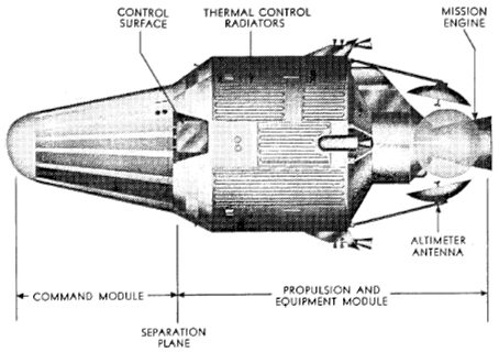
The Martin Model 410 design for Apollo comprised five basic parts: the LEPS Launch escape propulsion system; the CM Command Module or re-entry vehicle; the MM Mission Module; the PEM Propulsion and Equipment Module; and the Adapter section.
Modules such as the adapter section, LEPS, Command Module and Propulsion and Equipment Module were required for all versions of Apollo though their individual detail geometry and arrangement might differ greatly. The Mission Module, on the other hand, was not absolutely necessary for performing the functions expected of Apollo according to the NASA guide lines. The Model 410 design was based upon the modular approach (incorporation of a Mission Module) for many reasons. The most salient were that the modular approach gave more mission flexibility, led to a slightly lighter vehicle and gave a capability for the ultimate missions such as lunar landing. The various Apollo modules could be arranged in many ways.
PROPULSION AND EQUIPMENT MODULE LOCATION
The most important item of equipment contained within the PEM was the mission engine. It was, in general, desirable to have this at the aft end of the spacecraft with the engine on the centerline so that the thrust vector would nominally go through the Cg of the spacecraft. Configurations with the mission engine facing forward were not seriously considered since the engine would be exposed to aerodynamic heating and loads during ascent unless an auxiliary, jettisonable fairing were provided. If two or more engines were provided, placed outboard, fairings would be required and control of the spacecraft would be extremely difficult if one of the engines failed. Another factor to be considered was the configuration flexibility. If the propulsion system was confined to the rear part of the spacecraft, it was relatively easy to substitute alternate propulsion systems during the early missions if this was necessary to expedite the program.
For these reasons, the PEM was arranged with the mission engine at the rear of the spacecraft.
LAUNCH ESCAPE PROPULSION
The two most practical locations of the LEPS were forward of the escape vehicle or aft of it. The LEPS was placed forward of the escape vehicle on the Model 410 because this arrangement was stable, the LEPS was more easily jettisonable, it did not require more than one propellant bottle, the thrust loss due to nozzle cant was minimized and it was a system similar to that proven in Project Mercury.
COMMAND MODULE
The selected re-entry vehicle, the Model 410, had a hypersonic L/D ratio of 0.77 with a corresponding W/CdA of 142. Performance of five representative reentry vehicles with maximum L/D of 0.35 to 0.8 were considered before selection of the 410.
For the lowest L/D configuration, Mercury, entry at constant (L/D) maximum of 0.35 provided a 6 g limited corridor width of 12 naut mi. The maximum load factor for a 30-naut mi corridor was 11.5 g.
The L-2-C configuration, with a maximum L/D of 0.54, had somewhat g-limited corridors. The 6 g limited corridor width was 18 naut mi and the corridor maximum load factor was 9 g for entries at constant (L/D) maximum. The use of lift modulation during re-entry actually degraded the g-limited corridor performance of Mercury-type vehicles.
For the M-l, a forward facing cone with about the same maximum L/D as the L-2-C, the constant L/D g-limited corridor widths were essentially the same as those of the L-2-C. Maximum load factor experienced within the 30-naut mi corridor was about 9 g. However, if lift modulation could be used by this vehicle to increase g-limited corridor widths, 30-naut mi corridor entry would encounter a maximum load factor of 7 g with the use of full lift modulation.
The g-limited corridor performance of the remaining two vehicles, the W-1 and M-410, were nearly the same.
For the M-410 configuration, the 30-naut mi corridor maximum load factor was 9 g for constant CL max re-entry. This could be reduced to 5 g for partial modulation from CL max to (L/D) max or to 3 g for full modulation to CL = 0. With full lift modulation, a 6 g limited corridor width of 55 naut mi was obtainable. The constant CLmax re-entry gave the lowest maximum heating rates for a given corridor width. The maximum convective heating rate was 480 Btu/ft2/sec and radiation was 110Btu/ ft2/sec. To achieve the 55-naut mi corridor by full modulation, the maximum convective heating rate was increased to 740 Btu/ft2/sec and the maximum radiative heating rate was increased to 560 Btu/ft2/sec.
Partial lift modulation, however, could be used to obtain significant improvements in g-limited corridor widths with a relatively small increase in the maximum heating rates. Partial lift modulation could reduce both maximum load factor and maximum heating rates in comparison to constant (L/D) max re-entry for a given corridor width.
A single, circular, generously-sized hatch located near the center of the aft pressure bulkhead was the only personnel entrance to the M-410 re-entry vehicle. Components of the landing system, control system, and other equipment were arranged about this bulkhead so that the hatch was completely clear at all times. The 3-ft diameter of the hatch was adequate not only for personnel passage, but also would handle any equipment which must be placed inside the re-entry vehicle. Although M-410 had two stable flotation attitudes (upright and inverted), the hatch was above the water line regardless of orientation after a water landing. Problems associated with other types of reentry vehicles were numerous and in most cases were more serious.
The L-2-C re-entry shape, for example, was found to require two hatches. The shape had two stable flotation attitudes (small end submerged and heat shield end submerged) and was so shaped that a side hatch could be partially submerged regardless of the flotation attitude. The position of the stowed parachutes and of the LEPS tower made the small end impractical for a pre-launch entrance hatch, but the hatch was nevertheless necessary for egress after a water landing if the vehicle was floating with the heat shield end submerged. Consequently, this vehicle would need a hatch in the small end of the vehicle and another penetrating the heat shield at its most critical region.
The ideal spacecraft configuration was one that can be completely controlled in acceleration, velocity and trajectory from launch to landing, but such a design was impossible within the established weight constraints. Vehicle maneuverability in the post re-entry and landing phase somewhat reduced the need for accuracy in the guidance and control subsystems during re-entry (assuming that some form of position updating would be possible), permitted minimizing wind drift, and allowed the choice of the most desirable landing area within the available glide range. Several types of configurations were evaluated during the Apollo studies. T
(1) Airplane-type (fly-in landing vehicles using present pilot skills and control systems. These included a Dyna-Soar-type winged vehicle and two lifting bodies, a flat topped cone (M- 2B), and that interesting new family of shapes, the Lenticular, such as L-7. They all had the common problems of excessive spacecraft weight, booster compatibility and balance. They also required long, prepared-surface runways (over 5000 ft) because of their landing speeds, upwards of 130 knots. This high-speed landing requirement was not compatible with Apollo because of: (a) the "escape from the pad" situation, and (b) the possibility of all weather landing on poor terrain or rough water. These constraints could be met by auxiliary systems at the price of even more weight and a more complex development program. Accordingly, the airplane-type vehicles were discarded.
(2) The Rogallo Kite flexible wing. This device was particularly attractive in view of its proven feasibility from NASA model tests. In theory, this vehicle combined the long glide range, maneuverability and horizontal landing advantages with the light weight, compact stowage of the parachute. Considerable analytical effort was expended in evaluating its application to Apollo. The flexible wing was eliminated for the following reasons : (a) Considerable development and testing would be required to "man-rate" the system. (b) Erection under in-flight conditions was difficult since the required lengths of the keel and leading edge members were several times the length of the stowage area in the vehicle. (c) Difficulties in packaging while attaining the required vehicle center of gravity. (d) Absorption of landing loads, particularly under sea state 4 or unprepared terrain conditions with stall speeds above 40 knots. (Parachute vertical-descent velocity was essentially exchanged for a higher horizontal velocity.) (e) Pilot control was always required for a safe landing.
(3) Powered-rotor systems--an example of this type of system featured 30-ft diameter 3- bladed rotors with hydrogen peroxide-and-catalyst tip-rockets. The rotors were telescoped into a heat shielded, trailing storage cylinder 3 feet in diameter and 9 feet long. The major features of the system were: (a) drag modulation for controllable rate of descent, (b) glide capability, (c) steering capability during the glide, and (d) about five minutes of helicopter flight to cruise to a desirable landing site.
However, the landing maneuver required an accurate altitude sensor for height-above-ground measurement. Piloting technique required excellent training and coordination with little chance of surviving an error. This was also true of an automatic flare-out device. The extremely high weight and volume placed this system out of the application range for the Apollo vehicle. The stowage problems for the rotor blades would impose undesirable shape changes in the lifting body configuration. In addition, this system had no backup and depended on the rotor system to function without failure.
(4) Parachute landing systems. A number of assisted landing systems had been investigated for Apollo. These incorporated plain and steerable parachutes, various types of shock absorbing devices such as landing bags, and retrorockets. In view of the fact that some maneuverability was desirable for local obstacle avoidance, the steerable type parachute was chosen for Apollo. Selection of the retrorocket in conjunction with the parachute enables minimum touchdown velocity and crew load factors.
The main and backup parachutes systems were stowed on the aft bulkhead of the command module along with the retrorocket. The parachute was sized to give a nominal rate of descent of 40 fps. The retrorockets reduced the velocity at impact to a nominal 3 fps. In case of retrorocket malfunction, the landing shock was absorbed by crushable structure incorporated in the crew seats. This system overcame wind drift during its terminal descent, provided maneuverability to avoid local obstacles and required minimum pilot skill.
Weight of the various re-entry vehicle shapes considered for the command module were as follows:
- W-1: Heatshield: 1140 lbs. Heatshield Water And System: 180 lbs. Structure: 920 lbs. Aerodynamics Surface Or Flap: 251 lbs. Surface Controls: 258 lbs. Reaction Controls: 160 lbs. Landing System: 450 lbs. Auxiliary Power System: 527 lbs. Environmental Control (P&E): 310 lbs. Instruments: 260 lbs. Instrumentation: 98 lbs. Communications: 134 lbs. Guidance: 220 lbs. Scientific Equipment: 70 lbs. Furnishings And Equipment: 239 lbs. Crew: 630 lbs. Total Launch Weight Of Re-Entry Body: 5847 lbs.
- M-410: Heatshield: 1148 lbs. Heatshield Water And System: 180 lbs. Structure: 1075 lbs. Aerodynamics Surface Or Flap: 221 lbs. Surface Controls: 236 lbs. Reaction Controls: 160 lbs. Landing System: 450 lbs. Auxiliary Power System: 527 lbs. Environmental Control (P&E): 310 lbs. Instruments: 260 lbs. Instrumentation: 98 lbs. Communications: 134 lbs. Guidance: 220 lbs. Scientific Equipment: 70 lbs. Furnishings And Equipment: 239 lbs. Crew: 630 lbs. Total Launch Weight Of Re-Entry Body: 5958 lbs.
- L-2-C: Heatshield: 1108 lbs. Heatshield Water And System: 172 lbs. Structure: 870 lbs. Aerodynamics Surface Or Flap: 173 lbs. Surface Controls: 290 lbs. Reaction Controls: 160 lbs. Landing System: 450 lbs. Auxiliary Power System: 527 lbs. Environmental Control (P&E): 310 lbs. Instruments: 260 lbs. Instrumentation: 98 lbs. Communications: 134 lbs. Guidance: 220 lbs. Scientific Equipment: 70 lbs. Furnishings And Equipment: 239 lbs. Crew: 630 lbs. Total Launch Weight Of Re-Entry Body: 5711 lbs.
- L-1: Heatshield: 1190 lbs. Heatshield Water And System: 218 lbs. Structure: 1007 lbs. Aerodynamics Surface Or Flap: 188 lbs. Surface Controls: 155 lbs. Reaction Controls: 160 lbs. Landing System: 450 lbs. Auxiliary Power System: 527 lbs. Environmental Control (P&E): 310 lbs. Instruments: 260 lbs. Instrumentation: 98 lbs. Communications: 134 lbs. Guidance: 220 lbs. Scientific Equipment: 70 lbs. Furnishings And Equipment: 239 lbs. Crew: 630 lbs. Total Launch Weight Of Re-Entry Body: 5856 lbs.
- L-8: Heatshield: 1180 lbs. Heatshield Water And System: 187 lbs. Structure: 854 lbs. Aerodynamics Surface Or Flap: 295 lbs. Surface Controls: 315 lbs. Reaction Controls: 160 lbs. Landing System: 450 lbs. Auxiliary Power System: 527 lbs. Environmental Control (P&E): 310 lbs. Instruments: 260 lbs. Instrumentation: 98 lbs. Communications: 134 lbs. Guidance: 220 lbs. Scientific Equipment: 70 lbs. Furnishings And Equipment: 239 lbs. Crew: 630 lbs. Total Launch Weight Of Re-Entry Body: 5929 lbs.
- Flapped Mercury: Heatshield: 1158 lbs. Heatshield Water And System: 185 lbs. Structure: 912 lbs. Aerodynamics Surface Or Flap: 155 lbs. Surface Controls: 234 lbs. Reaction Controls: 160 lbs. Landing System: 450 lbs. Auxiliary Power System: 527 lbs. Environmental Control (P&E): 310 lbs. Instruments: 260 lbs. Instrumentation: 98 lbs. Communications: 134 lbs. Guidance: 220 lbs. Scientific Equipment: 70 lbs. Furnishings And Equipment: 239 lbs. Crew: 630 lbs. Total Launch Weight Of Re-Entry Body: 5742 lbs.
- W-1 Integrated: Heatshield: 1335 lbs. Heatshield Water And System: 201 lbs. Structure: 1156 lbs. Aerodynamics Surface Or Flap: 320 lbs. Surface Controls: 330 lbs. Reaction Controls: 205 lbs. Landing System: 575 lbs. Auxiliary Power System: 675 lbs. Environmental Control (P&E): 973 lbs. Instruments: 260 lbs. Instrumentation: 122 lbs. Communications: 159 lbs. Guidance: 220 lbs. Scientific Equipment: 175 lbs. Furnishings And Equipment: 413 lbs. Crew: 630 lbs. Total Launch Weight Of Re-Entry Body: 7749 lbs.
- L-2-C Integrated: Heatshield: 1477 lbs. Heatshield Water And System: 209 lbs. Structure: 1160 lbs. Aerodynamics Surface Or Flap: 251 lbs. Surface Controls: 403 lbs. Reaction Controls: 225 lbs. Landing System: 630 lbs. Auxiliary Power System: 675 lbs. Environmental Control (P&E): 973 lbs. Instruments: 260 lbs. Instrumentation: 122 lbs. Communications: 159 lbs. Guidance: 220 lbs. Scientific Equipment: 175 lbs. Furnishings And Equipment: 413 lbs. Crew: 630 lbs. Total Launch Weight Of Re-Entry Body: 7982 lbs.
- Lenticular: Heatshield: 1176 lbs. Heatshield Water And System: 193 lbs. Structure: 1247 lbs. Aerodynamics Surface Or Flap: 371 lbs. Surface Controls: 425 lbs. Reaction Controls: 185 lbs. Landing System: 622 lbs. Auxiliary Power System: 527 lbs. Environmental Control (P&E): 310 lbs. Instruments: 260 lbs. Instrumentation: 98 lbs. Communications: 134 lbs. Guidance: 220 lbs. Scientific Equipment: 70 lbs. Furnishings And Equipment: 239 lbs. Crew: 630 lbs. Total Launch Weight Of Re-Entry Body: 6707 lbs.
- M-2: Heatshield: 1841 lbs. Heatshield Water And System: 267 lbs. Structure: 1693 lbs. Aerodynamics Surface Or Flap: 872 lbs. Surface Controls: 600 lbs. Reaction Controls: 244 lbs. Landing System: 845 lbs. Auxiliary Power System: 527 lbs. Environmental Control (P&E): 310 lbs. Instruments: 260 lbs. Instrumentation: 98 lbs. Communications: 134 lbs. Guidance: 220 lbs. Scientific Equipment: 70 lbs. Furnishings And Equipment: 239 lbs. Crew: 630 lbs. Total Launch Weight Of Re-Entry Body: 8850 lbs.
With the PEM located in back and the LEPS in front, the two locations left for the re-entry vehicle were between the LEPS and the mission module or between the mission module and the PEM. The re-entry vehicle selected for the Model 410 was a forward-facing cone with a flat top. Arrangements which include the re-entry vehicle behind the mission module had somewhat better protection against meteorites since the heat shield was then protected by the structural shell but the complexity involved in separation of many parts during launch escape, the lack of direct access to the outside in emergencies and the fact that the re-entry vehicle had to be reoriented after separation for re-entry were reasons why this approach was not selected.
Some of the advantages were :
(1) Clean separation---only a single module was separated from the space vehicle in case of emergency.
(2) The arrangement allowed for growth versions of Apollo without re-entry vehicle or escape system redesign.
(3) The heat shield on the forward-facing body furnished good inherent protection against space radiation hazards.
(4) Guidance windows with a large field of view were possible.
(5) The re-entry vehicle attitude control nozzles could be used to reorient the spacecraft if the PEM system had failed and created an emergency.
(6) The command module need not be reoriented after being separated from the remainder of the spacecraft.
The main disadvantages of this arrangement was that the exposed heat shield was subject to damage by meteorites while in space. The effect of impingement on ablator performance would have to be studied by test. If the pits seriously degraded heat shield performance, some step such as the addition of a meteorite bumper would be necessary. The orientation of the crew was a significant factor in vehicle arrangement. However, life science studies showed that the crew -- properly restrained --- could perform the necessary functions during re-entry, whether facing forward or aft if the accelerations were not excessive.
The aerodynamic characteristics of the selected command module and the control methods used during re-entry would limit design re-entry load factors to 6g maximum.
The engine considered for the Apollo mission control propulsion system was an advanced version of the Pratt and Whitney LR-115 engine delivering a nominal thrust of 15,600 lb. It was concluded, that use of a single engine would mean that thrust chamber and turbopump failures were highly improbable for the burning time of the mission control engine (285 sec for lunar takeoff--the maximum case). A single engine with carefully designed systems and redundancies in selected areas was the preferred approach to the Apollo mission control propulsion system.
The propulsion and equipment module had to provide space and optimum locations for such items as : (1) Reaction control equipment. (2) Electrical power system. (3) Guidance equipment. (4) Communication and telemetering equipment. (5) Instrumentation and scientific equipment. (6) Furnishings and equipment. (7) Environmental controls. (8) Module separation equipment. (9) Propulsion system. (10) Structure. The module had to provide space for a mission module of 383 cu ft volume with an access hatch to the command module. Provision had to be made for the propulsion system liquid hydrogen fuel tank with a volume of 400 cu ft and the liquid oxygen oxidizer tank of 125 cu ft volume. Space and structural mounting was provided for the mission engine and its associated pumps, valves, fuel lines, etc. Mounting provisions were provided for the vernier engines at four locations as well as for the module separation rockets and the attitude rockets. Space was required for two 27-in. diameter spherical vernier propellant tanks, for a 32-in. diameter spherical hydrogen and a 25-in diameter spherical oxygen tank for the fuel cells of the electrical power system, and a 16.5-in. diameter spherical reservoir containing high pressure helium. Adequate space was required for the three fuel cells, water tanks, and other containers. Sufficient space was also required to mount on the outer surface of the module, solar radiators of 135 sq ft for the environmental control system and 9 sq ft for the fuel cells. Mounting provisions were provided for the guidance, communication, and telemetering equipment antennas which were in a retracted position during the boost phase and were extended for use for the space mission. Windows, camera ports were provided in the module.
The total volume requirements (cubic feet) of the larger items contained in the module were as follows:
- Mission module 383
- Hydrogen tank 400
- Oxygen 122
- Inter-module passage 7
- Fuel cell hydrogen tank 13
- Fuel cell oxygen tank 3.5
- Camera 7
- Vernier rocket fuel tanks 12
- Helium tank 1.8
- Fuel cells 5.5
- Flaps. (command module) 27.0
- Total -- 981.8
The above requirements dictated that the vehicle be oriented during its space travel with the nose of the vehicle facing the sun.
The weight of Model 410 was as follows:
- Command Module: 6954 lbs
- Heat Shield: 2078 lbs
- Structure and Controls: 1923 lbs
- Crew And Equipment: 2953 lbs
- Propulsion And Equipment Module: 5560 lbs (circumlunar version); 6080 lbs (lunar orbiter); 5166 lbs (lunar ascent stage)
- Mission Module Structure: 399 lbs
- External Structure: 600 lbs
Family: Lunar Landers. Country: USA. Bibliography: 2301, 4411.
 | Apollo Martin 410 Apollo Martin 410 re-entry vehicle shape. |
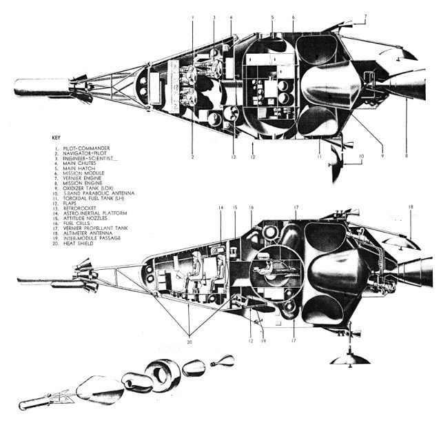 | Apollo Martin 410 |
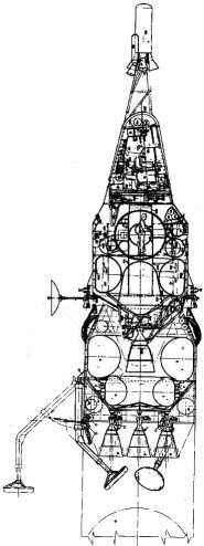 | Apollo Martin 410 Lunar lander version of Apollo Martin 410 |
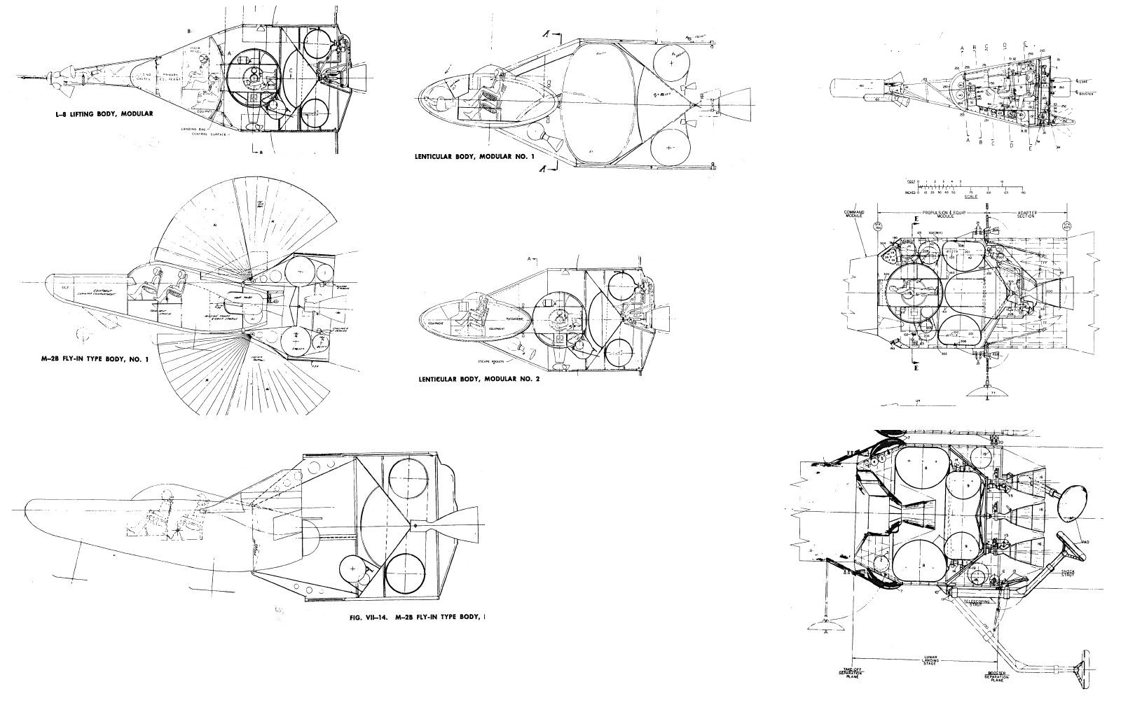 | Apollo Martin 410 Alternate Apollo configurations studied by Martin in 1961. |
 | Apollo Martin 410 Alternate Apollo configurations studied by Martin in 1961. |
Back to top of page
Home - Search - Browse - Alphabetic Index: 0- 1- 2- 3- 4- 5- 6- 7- 8- 9
A- B- C- D- E- F- G- H- I- J- K- L- M- N- O- P- Q- R- S- T- U- V- W- X- Y- Z
© 1997-2019 Mark Wade - Contact
© / Conditions for Use