
Home - Search - Browse - Alphabetic Index: 0- 1- 2- 3- 4- 5- 6- 7- 8- 9
A- B- C- D- E- F- G- H- I- J- K- L- M- N- O- P- Q- R- S- T- U- V- W- X- Y- Z
SLS BC-2720
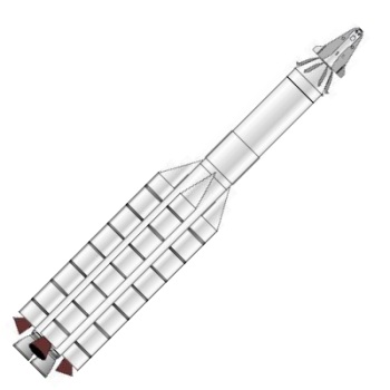 SLS BC-2720 Credit: © Mark Wade |
AKA: Space Launching System BC-2720. Status: Study 1961. Payload: 158,800 kg (350,000 lb). Thrust: 30,000.00 kN (6,744,000 lbf). Gross mass: 2,600,000 kg (5,700,000 lb). Height: 93.00 m (305.00 ft). Diameter: 7.62 m (24.99 ft). Span: 16.76 m (54.98 ft). Apogee: 560 km (340 mi).
NASA, not the Air Force, received the task of going to the moon and building large boosters. But the Saturn series was abandoned, while the BC-2720 resembles very much the Shuttle and Russian Energia configurations. Perhaps if things had been different...
BC Vehicle Launch Facility Considerations
Investigation of the launch pad requirements for a launch rate of two per month indicated that from 4 to 6 launch pads would be necessary depending on the launch site location and the means available for handling the booster. There were no existing launch pads capable of handling this vehicle, nor were there facilities capable of conducting static testing of the "C" booster and the launch of the complete Lunar Transport Vehicle. It was considered possible that by combining the capabilities for both static firing and launch in two of the pads required, a significant cost saving could be gained and an accelerated test program effected. This would provide a capability for the launch of the "C" booster with or without solid boost during R&D flight test and for early test missions of the Lunex Re-entry Vehicle. The development and flight test of the "B" booster was planned at Cape Canaveral during the development program.
It was assumed in the Lunar Transport Vehicle study that the manufacture of all boosters and the payload would be accomplished at existing factories. New and added facilities and equipment such as large forming brakes, special welding jigs, fixtures and machines, and large processing facilities would be required. In plants of sufficient size these facilities and equipment could readily be installed. Further investigation comparing the relative economics of manufacture at the launch site versus manufacture at existing facilities was required to insure an economical choice.
Assemblies having a diameter exceeding 12 feet or weighing over 200,000 pounds could not be transported over United States railways. A load of 78,000 pounds was considered to be the limit over selected highway routes. Inasmuch as both the "B" and "C" boosters of the Space Launch Systems had diameters in excess of 14 feet, transport from manufacturing plant to the launch site would have to be by barge. The large quantities of boosters and the special environmental protection required suggest that specially designed barges be constructed to transport these assemblies. Harbors and docking facilities would be required near the manufacturing facility and at the launch site.
By locating the launch facilities at or near Cape Canaveral for an easterly launch significant savings may be effected. The use of existing administrative capabilities, personnel housing, assured tracking facilities, and technical support areas would provide a saving in costs and in lead-time required for construction of support facilities. Similar gains could be made by locating launch facilities at Point Arguello for polar launch. This did not mean that Cape Canaveral and Point Arguello were the only reasonable locations for the launch site. In fact, by extending the Atlantic Missile Range in a westerly direction across the Gulf of Mexico it was conceivable that a launch site in the vicinity of the Corpus Christi Naval Air Complex would provide the full use of Atlantic Missile Range facilities with minimum overfly of foreign land masses. Likewise, extension of the Atlantic Missile Range in a northerly direction to the coast of South Carolina would provide a similar accommodation.
The logistic support for the launch rate as indicated in the study dictated that new propellant manufacturing plants be constructed at the launch site. Existing propellant manufacturing plants were inadequate and the launch rates mentioned would use the full capacity of a separate propellant manufacturing facility.
a. Propellant use rates for a 2 per month launch rate are estimated as follows:
(1) Liquid Hydrogen manufacture: 50 tons per day.
(2) Liquid Hydrogen storage at launch pad: 1.5 million pounds.
(3) Liquid Oxygen/Nitrogen Manufacture: 120 tons per day.
(4) Liquid Oxygen storage at launch pad: 4 million pounds.
Barges would be required for transport of boosters from the manufacturing plant to the launch complex.
A modified Integrated Transfer launch System was envisioned for the Lunar Transport Launch System. This approach would allow the complete integration and checkout of the "B" booster together with the Lunar Transport Payload in a protected environment simultaneously with the assembly and checkout of the C2720 booster combination at the launch pad. The size and weight of the BC2720 Space Launching Vehicle precluded the transfer of the completely assembled Lunar Transport Vehicle from an integration building to the launch pad. It was feasible, however, to mate and integrate the "B" booster with the Lunar Transport Payload inside the protected environs of an integration building and, when completed, transfer the "B" booster and payload assembly to the launch pad for mating with the C2720 assembly.
This could best be accomplished by a cliff-side location or extending a ramp from the integration building to an elevation at the launch pad approximately equal to the height of the C2720 stage. The assembly and checkout of the C2720 vehicle could be accomplished in two ways depending on the specific location of the launch pad and its accessibility to navigable waters. For a launch pad having no direct access to navigable waters, the assembly and mating of the solid segmented motors to the "C" booster would be accomplished at the launch pad. The extended time necessary to accomplish this assembly and checkout accounts for the difference in the numbers of pads required. It was estimated that 6 launch pads would be needed for this plan.
For a launch pad having direct access to navigable waters, the assembly and mating of the solid segmented motors to the "C" booster could be accomplished at an interim integration building located some distance away from the launch pad. After assembly and checkout, the "C2720" combination would be transported by a barge to the launch pad and mated to the "B" booster and payload assembly. By using this approach it was estimated that 4 launch pads would be adequate for the 2 per month launch rate. Final confidence checks and integration of the booster and facility interface would be accomplished at the launch pad.
The TNT equivalent of vehicle propellants was estimated in the following manner. The TNT equivalent of the liquid propellants was taken at 60% of the total LOX/LH2 load for all stages. This was the figure currently used at Atlantic Missile Range for TNT equivalence for LOX/LH2. In this case, because of the great quantities of propellant involved, this degree of mixing was unlikely and the 60% figure would be conservative.
Solid propellants were taken at 100% of the propellant weight. It was also considered that detonation of the solid propellants may cause the subsequent detonation of liquid propellants and vice versa; but, the simultaneous detonation of all propellants was not likely to occur. This philosophy resolved to consideration of TNT equivalents of liquid propellants and solid propellants separately and they were not additive. The TNT equivalent of one of the four segmented solid assemblies was 680,000 pounds. The 60% TNT equivalent of the total liquid propellant load was approximately 1,300,000 pounds. Using the highest TNT equivalent (1,300,000 pounds) the inhabited building distance must be approximately 2 1/2 miles from the launch pad and minimum pad separation must be approximately 1 mile.
For an inhabited pad adjacent to a launch operation, pad separation would be 2 1/2 miles. It was obvious that the real estate problem would be extensive. For a coastal location of "C" launch pads up to 18 miles of continuous coast line would be required for a distance of 3 miles inland. These distances could be decreased by creating a buffer between the pads. Locating the launch pads in ravines or indentations in cliff aide launch locations might substantially reduce the land areas required. The selected location and orientation of the integration building and other support facilities to take best advantage of topography would do much to decrease distances and reduce costs.
The repeated launching of similar payloads in the Lunar Transport Launching System and the extended time between launches from each pad indicated that a central launch control for all pads might be desirable. To avoid analogue signal line driving problems and to allow greater distances than normal between the pads and the common blockhouse it was possible to use digital control for launch pad checkout and launch. Analogue to digital conversion would essentially be accomplished at each launch pad and transmitted to the blockhouse via digital data link.
With vertical mating, assembly and detailed checkout in the vertical assembly integration buildings, only gross, survey type testing or a simulated countdown and launch would be performed at the launch pad, since test and vehicle subsystem sequencing systems could be installed in both areas. Present day checkout methods, because of the many manual controls and long time spans involved, would not provide sufficient assurance of the high reliability of the complex integrated systems expected in the Lunar Transport Vehicle.
LEO Payload: 158,800 kg (350,000 lb) to a 560 km orbit at 28.00 degrees. Payload: 60,800 kg (134,000 lb) to a translunar trajectory.
Stage Data - SLS BC-2720
- Stage 1. 4 x SLS SRB 2720. Gross Mass: 366,716 kg (808,470 lb). Empty Mass: 56,000 kg (123,000 lb). Thrust (vac): 8,130.000 kN (1,827,690 lbf). Isp: 260 sec. Burn time: 100 sec. Isp(sl): 235 sec. Diameter: 4.57 m (14.99 ft). Span: 4.57 m (14.99 ft). Length: 51.00 m (167.00 ft). Propellants: Solid. No Engines: 1. Status: Study 1961. Comments: Four such 180 inch segmented solid rocket motors provided first stage thrust for Project Lunex. A liquid propellant first stage was considered as an alternative, but the solid stage was the baseline. Empty mass, specific impulse estimated.
- Stage 2. 1 x SLS Stage C. Gross Mass: 825,000 kg (1,818,000 lb). Empty Mass: 58,000 kg (127,000 lb). Thrust (vac): 10,673.322 kN (2,399,458 lbf). Isp: 428 sec. Burn time: 350 sec. Diameter: 7.62 m (24.99 ft). Span: 7.62 m (24.99 ft). Length: 53.00 m (173.00 ft). Propellants: Lox/LH2. No Engines: 2. Engine: M-1. Status: Study 1961. Comments: Launch vehicle core stage for Project Lunex. Masses estimated based on optimum apportioning of B+C stage total masses. Thrust, engines estimated based on requirements.
- Stage 3. 1 x SLS Stage B. Gross Mass: 160,000 kg (350,000 lb). Empty Mass: 11,200 kg (24,600 lb). Thrust (vac): 1,778.651 kN (399,857 lbf). Isp: 424 sec. Burn time: 345 sec. Diameter: 7.62 m (24.99 ft). Span: 7.62 m (24.99 ft). Length: 25.00 m (82.00 ft). Propellants: Lox/LH2. No Engines: 2. Engine: J-2. Status: Study 1961. Comments: Translunar injection stage for Project Lunex. Masses estimated based on optimum apportioning of B+C stage total masses.
Family: orbital launch vehicle. Country: USA. Stages: SLS Stage B, SLS Stage C, SLS SRB 2720. Agency: USAF.
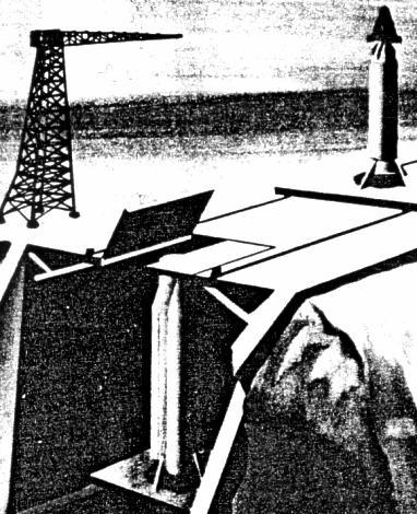 | Lunex Launch Pad Lunex Launch Pad with BC-2720 vehicle in assembly. The Lunex upper stage package has been integrated with the 'B' stage and will be installed by crane on the C-2720 booster and core stage assembly already installed in the cliff-side pad. |
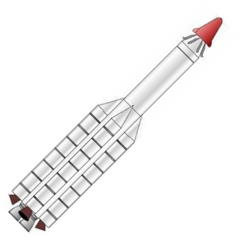 | Lunex BC-2720 LV Lunex BC-2720 launch vehicle. |
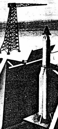 | Lunex BC-2720 LV Lunex BC-2720 launch vehicle installed on the pad. |
Back to top of page
Home - Search - Browse - Alphabetic Index: 0- 1- 2- 3- 4- 5- 6- 7- 8- 9
A- B- C- D- E- F- G- H- I- J- K- L- M- N- O- P- Q- R- S- T- U- V- W- X- Y- Z
© 1997-2019 Mark Wade - Contact
© / Conditions for Use