
Home - Search - Browse - Alphabetic Index: 0- 1- 2- 3- 4- 5- 6- 7- 8- 9
A- B- C- D- E- F- G- H- I- J- K- L- M- N- O- P- Q- R- S- T- U- V- W- X- Y- Z
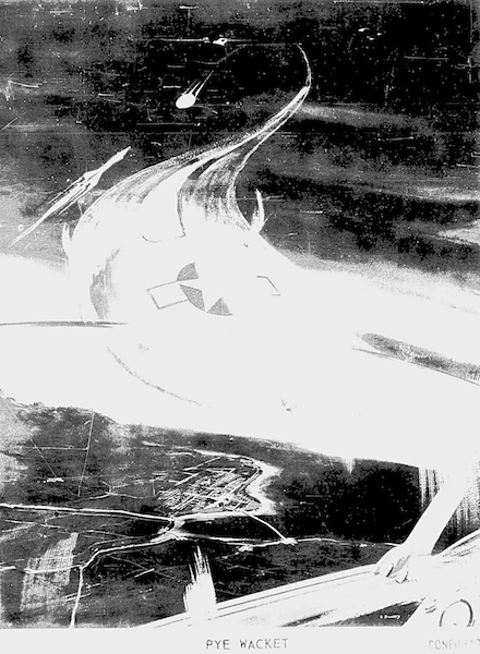
Pye Wacket
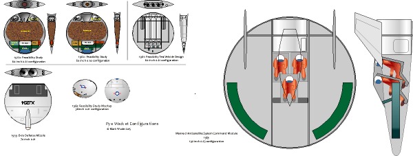
Pye Wacket
Pye Wacket Overview
Credit: Manufacturer Image
Lenticular Defense Missile
It was 1957 and Eglin Air Force base, the US Air Force's center for development of airborne weaponry, was at work developing a Defensive Anti-Missile System for bombers faced with penetrating future Soviet air defenses. The United States felt surrounded by threats and saucers were literally "in the air". The area around Eglin experienced a rash of UFO sightings.

The Report on Unidentified Flying Objects by the former head of USAF Project Blue Book, presented the possibility that flying saucers were real hardware with incredible performance. At NACA Langley, Alan Kehlet was promoting his flying saucer design for manned spacecraft, and Paul Hill was developing a theory of flying saucer propulsion based on sighting reports.
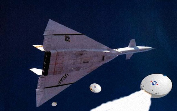
In October the launch by the Soviet Union of Sputnik, the first artificial satellite of the earth, shook the American defense establishment to its core. Classified assessments of the time indicated that the B-52 bomber just shipping would only be able to penetrate the Soviet air defenses for a few years, and even the follow-on B-70 Mach 3 bomber might need some kind of active defense. The requirement was for an 'omnidirectional' device that after release from a bomber could fly in any direction to take out air-to-air or surface-to-air missiles and manned interceptors. It was in this milieu that the Eglin researchers conceived of a radical flying vehicle based on the classic flying saucer: a lens-shaped or 'lenticular' configuration.
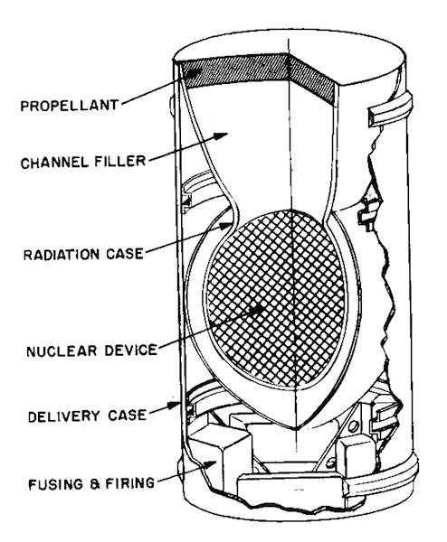
The Air Proving Ground Center (APGC) at Eglin had the task of providing the guidance and control necessary to turn the lenticular device into a "defensive missile with omnidirectional launch capability". To ensure neutralization of any type of threat, Eglin advocated the use of a miniature nuclear warhead using an enhanced radiation warhead (then known as "neutron dudding"). This "dudding by neutron kill" approach would render the warhead of an interceptor missile inoperative without exploding it. RAND, the USAF's think tank, had concluded that an interceptor missile warhead fuze could not be designed that could withstand the dudding effect. They also believed that fractional-yield bomber defense missile warheads could be built with predictable blast and radiation effects.
In fact, miniature nuclear weapons that could be tailored to mainly emit certain types of radiation, and to channel that radiation directionally, were already on the drawing boards. Los Alamos physicist Theodore Taylor was the leading designer of tailored and miniaturized nuclear devices of this kind. The W54, first tested in 1957, had a diameter of 10.75 inches and weighed around 50 pounds (23 kg). Smaller devices using less fissile material and with channeled explosions were being developed for the Orion interplanetary spaceship.
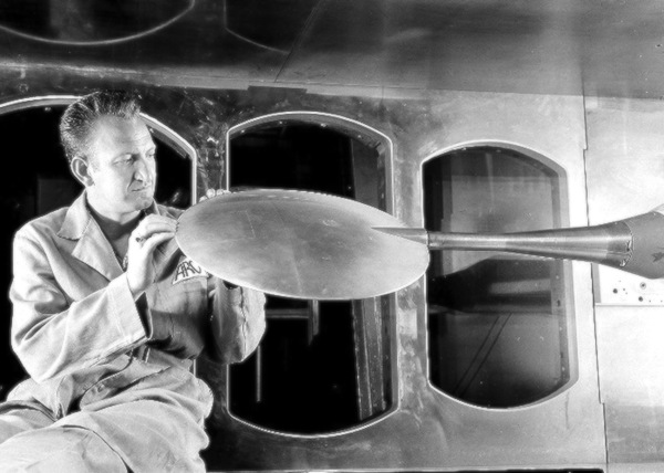
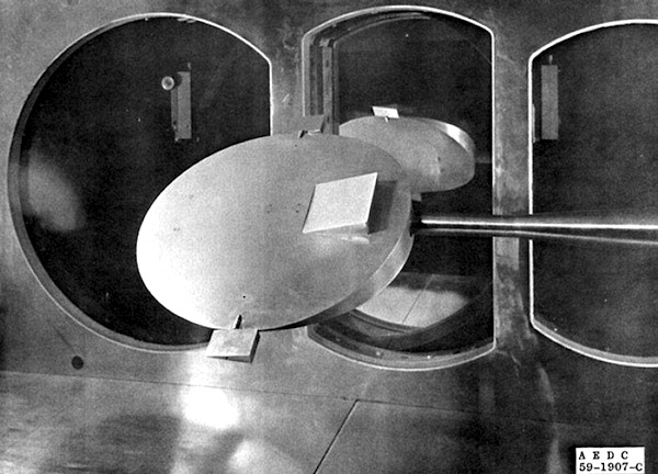
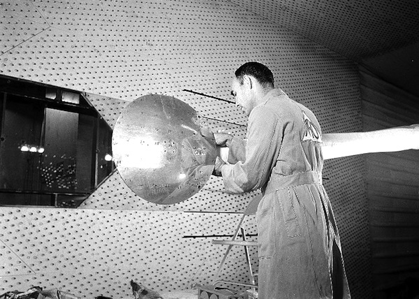
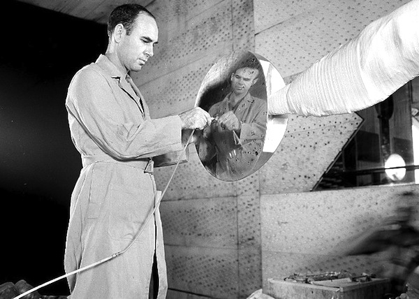
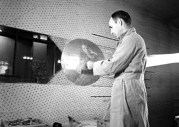
Eglin's Technical Planning Group first conducted an in-house preliminary study. Tests of the design were undertaken at Wind Tunnel E-l of the Gas Dynamics Facility, Arnold Engineering Development Center in Tennessee. These verified the preliminary aerodynamic calculations. Photos from this series of tests, released over fifty years later, were the first public evidence of the project. They show the first concept, the pure flying saucer shape, later dubbed Model I.
Testing indicated better stability and more volume for components for a blunt lenticular configuration (later Model II). The effectiveness of different aerodynamic controls were also tested.
Leading edge deflection was proposed for maneuvering the missile in flight as a result of the "in house" test program. A unique launch method was proposed, with the saucers stacked like LP records on a spindle within the bomb bay, rotated to the proper heading, and then ejected from the spindle.
Part of the development contract for the B-70 Mach 3 bomber required North American to evaluate active defenses for the aircraft. The basic requirement for the aircraft was that it be fast enough, and fly high enough, so that Soviet air defenses would have no chance of destroying it. Therefore it was somewhat grudgingly that North American completed a B-70 Active Defense Feasibility Study in March 1959. Eglin's Model II "Lenticular Defense Missile" (LDM) was one of three devices reviewed.
At this point in the program North American was struggling to achieve specified range in the B-70 aircraft. Exotic 'zip' fuels might achieve the goal, but meanwhile every ounce on the aircraft mattered. So the contractor determined that carriage of five to eight defense missiles could provide a "sizable improvement in survival..." however only "...if the system could be installed with no range penalty" (!) Either of the conventional missiles would create a 675-nautical-mile range loss, and the LDM, 780 miles. North American then estimated that bomber defense missiles would only add about 10 percent to the B-70's penetration effectiveness.
The study concluded that "...this improvement was too small ...to warrant...the addition of an active defense system at this time." However they also "...concluded that the threats against which an active defense mechanism would be required to operate were, in order of probability, a Mach 3 interceptor carrying a GAR-9 type missile, area-defense surface-to-air missiles, and point-defense surface-to-air missiles." In fact the Soviet Union demonstrated the last of these capabilities only a year later, when they shot down Gary Power's high-altitude U-2 spy plane. This vulnerability of the B-70 (absent active defense missiles) contributed to several budget cutbacks, and finally cancellation of the aircraft.
North American nevertheless found that the LDM's "unique shape and light weight" gave it
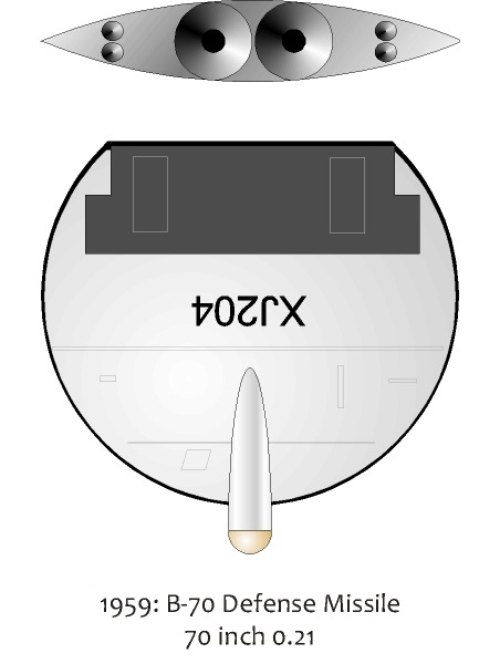
under certain conditions, performance capabilities which the more conventional missiles are hard put to equal. It can be launched in any direction since the drag is, in effect, the same no matter what its orientation is to the relative wind. While a conventional missile must be launched with its nose pointed forward and turned to attack a target in the rear hemisphere, the LDM Lenticular Defense Missile may be headed in the right direction at launch and all of its boost used to propel it toward the target.The Eglin saucer concept considered by North American was 70 inches in diameter, nine inches deep, and was powered by two solid propellant rockets producing 10,200 pounds of thrust. An infrared tracking unit with a "jettisonable cover for initial phases of the flight . . . was installed in its nose."
Range was approximately 72 nautical miles, weight was 510 pounds and maximum velocity 6,700 feet per second. Headed in the proper direction at launch, it would generally follow a pre-programmed inertial trajectory until burnout. During this phase the missile nose was not necessarily pointed at the target "since the best path is a function of the velocity vectors," but at burnout "spoilers" were to be "differentially actuated to turn the LDM so that the target will be within the cone of view of the IR seeker." At this point an aerodynamic cover/heat shield would jettison and the cylindrical section housing the hemispherical heat-seeker would deploy forward of the leading edge of the missile. The bomber's weapons control officer could alter the aspect of the seeker head by controlling a set of gimbals via datalink and retained, to this point, an overriding authority. Once the target had been acquired by infrared, the seeker head in the missile guided it autonomously to its target.
In addition, although North American was impressed with the "center post mounting and ejection method of the LDM," the company was concerned about the "very uniqueness" of the system and wanted "further detailed study." This launch system was described as follows:
At launch, the inner threaded post will rotate to translate the missile downward to the launch position, whereupon the entire shaft will rotate to turn the missile into the desired launch heading. The door will then open and the missile will be ejected by means of a percussion ejector. Rocket motors will not be ignited until the missile is safely clear of the aircraft.North American to believe that "there may be sizable improvement in performance through development of this type of missile." The contractor held, however, that "insufficient results" at that time prevented establishment of a defined configuration and evaluation of "performance improvements which may be possible through alterations to the configuration tested." "Doubtful areas" were "stability, and drag versus angle of attack data."The ejector piston will run the length of the center post with the breech at the top. A rotating, revolver-type magazine will contain all the charges needed to eject the full load of missiles and will revolve automatically for each shot.
Contoured about the missiles will be a fuel tank which will occupy any remaining usable volume. Capacity is estimated at 1500 gal.
The missile umbilicals will be routed through the center post. Since the outer portion of the post is used as a sliding guide to diametrically position the missiles, some leeway in shape is possible. Accordingly, a cavity will be formed in this outer shell to accommodate the umbilicals. Some twist will be necessary in the umbilical, but since maximum rotation of the missile to launch will be 180 degrees, the umbilical design problem is somewhat reduced.
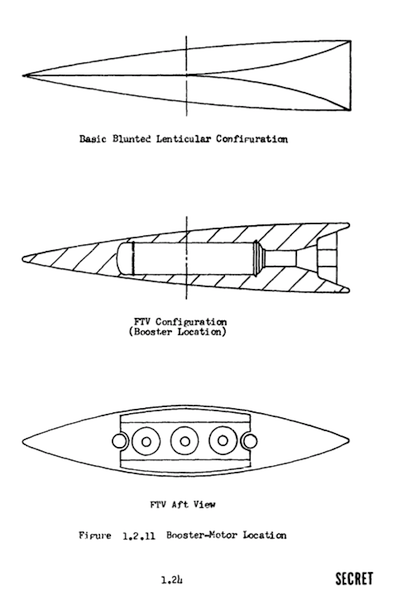
Eglin did not share North American's negative assessment of the LDM, and continued work to clear up the uncertainties. Funding was obtained to move the concept into development. An unclassified request for proposal was circulated to industry on 23 March 1959, leading to several proposals being received in April. Convair Pomona received contract AF 08(635)-542 in June 1959 for a Phase I six-month Feasibility Study. Additional project phases would be exercised as contract options. Phase II would be design of a Feasibility Test Vehicle. Phase III would be the actual rocket-sled test of the FTV and design concepts for use of the design for spacecraft and ICBM applications. The classified ARDC Project 3811 was given the public code name Pye Wacket.
Origin of the Name

There are various guesses and stories of how the project got such an unconventional name, related to the unknown and occult. Pye Wacket was the name of the cat who was the familiar to the witch played by Kim Novak in the film Bell Book and Candle. The comedy was released on Christmas day 1958, with the love interest played by Strategic Air Command Colonel James Stewart (promoted to Brigadier General on 23 July 1959). One story (via Dennis Jenkins) was that the name was selected by a secretary in the project office who had seen the movie. Another (via Joel Carpenter) was that Colonel Stewart had a hand in the naming. He certainly had the connections to be aware of the program and was present at the roll-out of the B-70 on 11 May 1964...
Either way, Pye Wacket was the small protector of her mistress:
Stewart: Is that your cat? I've seen him on the stairs, watching me come in and out. What's his name?However the name goes back much farther. The writer of the original 1950 stage play had come across the memoirs and court transcripts of the infamous Matthew Hopkins, the Witchfinder General, responsible for the trial and execution of over 300 women as witches in 17th Century England. In 1644 Hopkins began his murderous three-year career by prosecuting a woman who was assisted by several familiars and imps, one of then named Pyewacket:
Novak: Pyewacket.
Stewart: How's that?
Novak: Pyewacket.
Stewart: Pyewacket. Well, how do you do? (Pyewacket lashes out as he reaches to stroke her) Bad cat!
Novak: I'm glad he didn't scratch you.
Stewart: No. That's all right.
Novak: He doesn't have very good manners. It's just because you're a stranger.

...in March 1644 ... this Witch confessed severall other Witches, from whom she had her Imps, and named ... as Elemanzer, Pyewacket, Peckin the Crown, Grizzel Greedigut, &c. which no mortall could invent ... 29 were condemned at once, 4 brought 25 Miles to be hanged ... for sending the Devill like a Beare to kill him in his garden...No matter the origin, the name gave the black project a permanent linkage with the fantastic.
The Pye Wacket Project Team
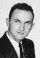
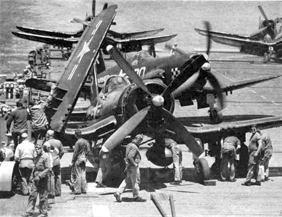
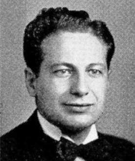
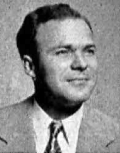
Convair selected 26-year old Preliminary Design Engineer Earl Eugene Honeywell to head the project within the company. Honeywell was born on 15 February 1933 in Cherryville, Kansas to George and Mary Honeywell. His father was a repairman and headed a family of three sons and two daughters. Earl enlisted in the Marine Corps Reserve at age 17 on 26 June 1950, the day after the outbreak of the Korean War. After a six month deferment, he was activated, trained, and sent to Korea. He served with VMF-312, a Marine fighter squadron equipped with F4U Corsair fighters, which flew continuous combat missions from the carriers Bataan, Bairoko, and Sicily for the duration of the war. He remained in the Marine reserves until 18 August 1958.
After the war he entered the University of Wisconsin, Madison, where he met his future wife. Claudette Ann Elwell, who was born on 14 May 1934 in Imperial, Nebraska. They were married in Council Bluffs, Iowa, on 25 July 1953. Earl and his wife moved to Seattle, Washington, where he studied aeronautical engineering at the University of Washington while working as a draftsman at Pacific Northwest Airlines.
Following graduation in 1957, he was hired by Convair Pomona, and the family, now including their first daughter, moved to Pomona, California. A second daughter was born in September 1957, just months after their arrival.
Convair Pomona had been built in 1952 to handle the company's burgeoning work for the US Navy's surface-to-air missile programs. Here the mainstays of the US Navy's air defense, the Terrier and Talos missiles, were built. In the process Pomona developed a broad experience base in rocket propulsion and missile guidance. In the mid-1950's Convair Pomona sought to branch out, snaring the US Army's Redeye program for the first man-launched infrared-guided surface-to-air missile in 1958.
Honeywell must have been an impressive young man, because he was tagged to lead the Pye Wacket project at Convair (During the course of the program Convair was purchased by General Dynamics. Both corporate names appeared on various documents during the transition).
In the critical aerodynamics area he was supported by William Hatalsky, who was born on January 7, 1924 in Russelton, Pennsylania, to Ephimia and Wasilli Hatalsky. His parents had emigrated from Zelezniki, Russia, in 1913. His father moved the family to Hamtramck, Michigan where he found work as a bolt tightener in an automobile factory. William served during World War II as an enlisted man in the US Army in the European theater. After the war he studied aeronautical engineering at the University of Detroit, graduating with a Master's Degree from the University of Michigan in February 1951 and marrying Virginia Dromowicz on the same day. His 38-year career as an aerodynamicist begain with work on the Boeing B-47 bomber, followed by stints at Aerojet General in El Monte, California, before coming to Convair Pomona. Hatalsky was known for his sharp wit and sense of humor.
Also assisting Honeywell was Edward Velton, born in Birmingham, Alabama on March 4, 1926. He served in the US Army as a Flight Engineer in World War II, and like Hatalsky graduated from the University of Michigan with a Master's of Science in Engineering. He was became an expert at Pomona in preparation of proposals for the government. In later life he authored four professional books and became a consultant on Proposal Development.
The second lead on the project was a D R Geise, for whom no information can be found. All of these young engineers and their families lived in new housing developments in nearby Whittier, California.
Pye Wacket Phase I
The Phase I report, issued on 14 January 1960, was extremely comprehensive considering the time allotted. This may have represented prior work. Convair devoted more than three years of effort on company funds on the Redeye missile before obtaining the contract. The same may have been true for Pye Wacket. In this view, the Eglin work represented the government independently verifying the design before releasing funding to Convair to take it to the hardware stage under the charade of a competitive contract. This was relatively common practice. However if true, it would be rather disingenuous for Convair to claim that the idea "...originated with the (Eglin) Technical Planning Group..."
In any case, the Phase I report elaborated on the earlier aerodynamic analysis and testing with computer work and additional wind tunnel tests. The design was compared with existing missiles and found far superior. Convair prepared preliminary design layouts, built a mockup, and did proof-of-concept electronics packaging. Detailed studies were conducted in the areas of aerodynamics (including wind tunnel tests), aerodynamic heating, propulsion, control systems, structures, and missile performance. The conclusion was that Convair's 'Model III', a variation on Eglin's Model II "blunted lenticular" configuration, had far and away the best performance. Limited guidance and launch studies were conducted. Convair concluded that Pye Wacket "...showed significant advantages for the lenticular configuration, compared to conventional missiles, particularly as related to omnidirectional launch and high maneuver capability".
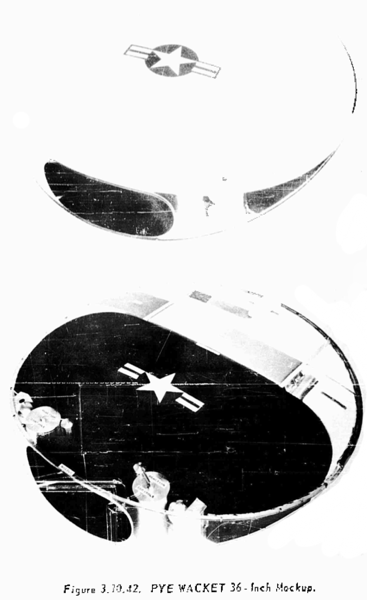
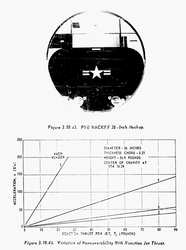
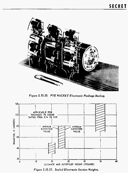
Nominal vehicle configurations were determined, based on the parametric data generated, and design feasibility layouts with supporting data were shown for these configurations. Design scaling information was determined for preliminary weight and performance estimates of various-size Pye Wacket missiles. A mockup of Convair's recommended 36-inch diameter version of the missile was built.
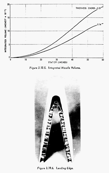
Based on these analytical studies and wind tunnel tests, Convair's improved Model III shape was developed. The drag, lift, and stability characteristics of this configuration were far superior to Eglin's Model I and Model II. These performance improvements were achieved primarily by moving the maximum thickness point of the missile to the aft end. Configurations with a thickness to diameter ratio of 14% and 21% were studied in detail. The 21% configuration naturally provided more volume for internal components.
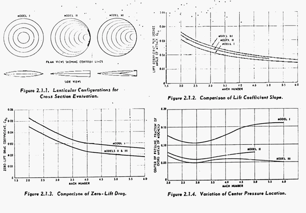
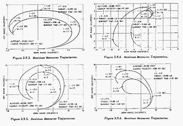
The Model III aerodynamics were compared with conventional missile configurations. Pye Wacket was found to turn in half the radius of the conventional missiles used in the comparisons.
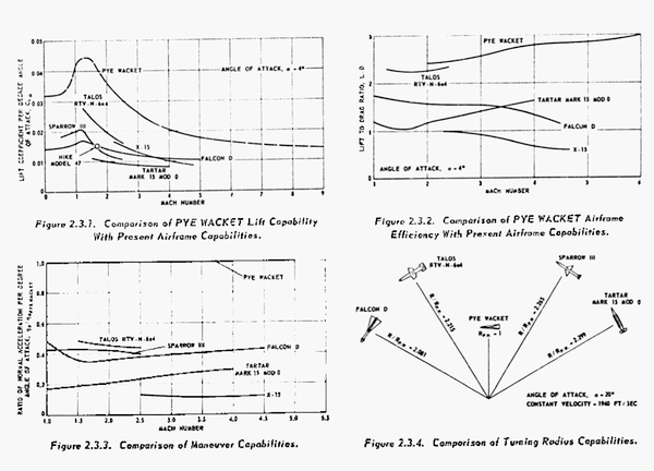
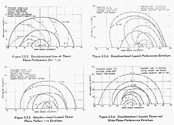
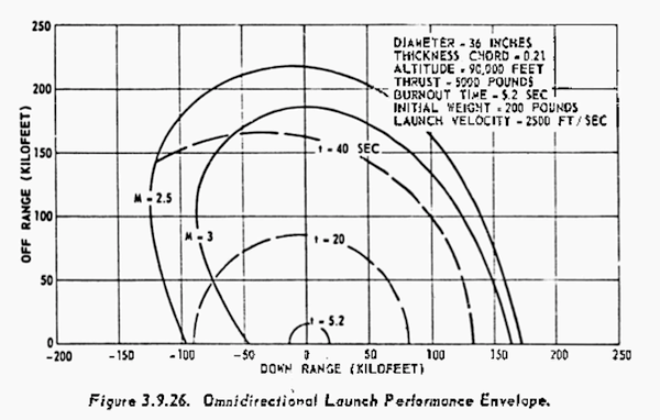
The performance investigation showed that using omnidirectional launch, protection for manned aircraft could be obtained for all approaches of attack. Depending on the altitude of the bomber, air-to-air ranges of 8 to 24 miles could be obtained in all directions from the bomber. A reduction in missile size from 60 inches to 36 inches could be made without an excessive penalty in stand-off distance if advanced techniques and materials were used. High maneuver capabilities were available from the Pye Wacket configuration at all altitudes studied. Detailed studies of required ejection forces using Convair's extensive data from their supersonic B-58 bomber showed clearance from the bomber after launch in any direction would not be an issue.
Propulsion
Trade studies were undertaken to consider the feasibility of turbojet, turbo-rocket, ramjet, external combustion ramjet, liquid rocket, and solid rocket propulsion for Pye Wacket. The turbojet systems could not function at the Mach 3 to 7 envisioned for Pye Wacket. A ramjet would require too large an intake area and be too heavy. The external combustion ramjet was a possibility, but any operational use was too far in the future. That left the liquid or solid rocket approaches.
Either a liquid-rocket or a unique pancake-shaped solid rocket motor would take full advantage of the internal volume of the saucer. Multiple tapered solid-rocket motors or cylindrical solid rocket motors would require less development, but would not take full advantage of the internal volume.
The multiple cylinder solid propellant configuration would have the shortest development time and risk. A survey of then-available rocket motors showed existing propellants were adequate. Only the swivelling nozzle manifold represented an extension of the state-of-the-art.
The pancake solid propellant motor represented a greater development risk. Problems to be solved included design of a lightweight pressure vessel and a suitable grain configuration; methods of coring and casting such a grain; propellant with a reasonable environmental temperature range; and reliable ignition of the unusual configuration.
The pancake motor casing would naturally be heavier than conventional solid motors to contain the 250 psia internal pressure. The propellant fraction for a 21% pancake motor design would be 0.689 compared to 0.798 for conventional cylindrical motors. However it would provide 426 pounds of propellant, and 112,038 pound-sec of impulse, more than double that of any arrangement of cylindrical motors.
The low-chamber-pressure pressure-fed liquid propellant alternate would be similar to storable liquid systems using pressurized tanks such as the Guardian series developed by Thiokol's Reaction Motors Division. The primary problem, as in the pancake solid, would be in the pressure vessel design. Attention woud be required to insure positive expulsion of the propellants at all attitudes and under a high-G environment. Since engine operating duration would be short, an insulated chamber or one employing film cooling would be adequate. Stable operation at low chamber pressures was verified on propulsion systems for space vehicles that operated satisfactorily at pressures less than 100 PSI. A liquid propellant system would have only 4% better performance but be more complex, expensive, and have storage and maintenance issues when kept in readiness for years under extreme temperature variations.
Preliminary proposals obtained from a number of major rocket engine manufacturers substantiated the performance numbers used in the study. The performance numbers were realistic and attainable in the 1961-62 time period. Successful ignition and launch of rocket engines pointed into high velocity air streams had already been demonstrated in the Wagtail program. Convair concluded that the pancake-solid rocket motor was the preferred approach, although a liquid rocket system was also designed.
Control Systems
Convair's Pye Wacket control system investigation found that the aerodynamic control surfaces planned by Eglin were actually unsatisfactory for use on a circular planform missile. Reaction controls using fixed auxiliary jets were feasible and provided acceptable response times and a simple autopilot design. Maneuvers unobtainable with conventional configurations were possible with Pye Wacket using reaction controls at extremely high altitudes.
The launch sequence differed from that envisioned by Eglin and used in the B-70 study. Before launch, the missile would be oriented in azimuth, on the launcher, so that the missile's infrared seeker would be pointed at the target. This seeker would be behind conformal windows flush with the skin of the missile (therefore no seeker cover had to be jettisoned as in the earlier design).
Only after the seeker locked onto the target would the missile will be ejected. The omnidirectional missile would be subjected to a very large angle of aerodynamic yaw. In the worse case, it could be ejected pointing opposite the direction of flight of a Mach 3 bomber. Therefore the missile was initially stabilized using an inertial device with three rate gyros until thrust from the rocket motor built up forward speed.
After that point, guidance switched over to inputs from the infrared seeker. Bang-bang reaction controls would control the roll and pitch of the saucer. Yaw changes would be obtained by rolling to the required attitude and then pitching to obtain the required yaw maneuver. The proposed combination of seeker and autopilot give proportional navigation homing. The simple missile instrumentation included the seeker, an aerodynamic yaw-sensor, and three rate gyros with electronic integration of all three rate gyros during the launch phase.
Structures and Thermal Protection
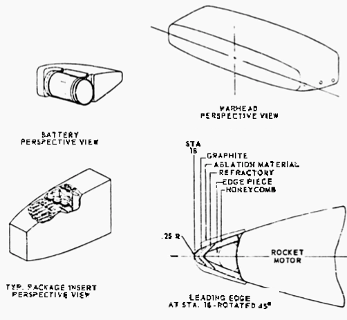
Pye Wacket would be subject to very high aerodynamic heating during its high-speed, high-G intercept. Use of a teflon ablative covering on the missile's skin was found to be superior to heavier and more complex transpiration cooling. Only 30 pounds of teflon would be required for the largest 60-inch diameter configuration. The sharp leading edge would require a graphite cover for the bomber defense mission. Other applications requiring less missile performance could use a blunt leading edge covered with teflon ablative material.
Follow-on Pye Wacket designs could use a double wall consisting of skin in which a liquid coolant was packaged. The coolant would boil off as heat was absorbed. The vapor would be ejected through the skin, but ducted to the aft end of the missile to contribute thrust.
Phase I work included vibration testing of a structural prototype. The material investigation selected B-120 titanium for the structure. This material could be formed, machined, chemically etched, and molded. It possessed strength-to-weight advantages of 20 to 60 percent over 15-7Mo stainless steel in the temperature range of 800 deg F to 1000 deg F. Stabilization of the upper and lower pressure vessel surfaces was accomplished by posts. Posts were selected because they could be inserted after the tank was assembled, and did not sectionalize the tank as would bulkheads.
Aero-elastic studied concluded that that there would be no serious coupling with the autopilot. Some form of internal panel support through use of a corrugated inner skin, additional ribs, or sandwich type construction was required to prevent destructive panel flutter in a large portion of the flight profile. Honeycomb was shown to be 20% lighter than corrugated skin.
Detailed Design
A nominal 60-inch diameter missile was selected for design layouts due to the emphasis placed on this dimension by Eglin. Only thickness-to-chord ratios of 14 percent and 21 percent were considered for these layouts since the performance of missiles with these thickness ratios spanned the range of interest based on maximum range capability, minimum time-to-target intercept, and packaging limits.
Using these two thickness ratios, approximate missile weights and performance capabilities were determined as functions of the missile diameter. The range of missile diameters considered was limited to 30 inches to 120 inches. The scaling was accomplished by utilizing the weight determination of the nominal 60-inch diameter missiles of 14 percent and 21 percent thickness ratios as the bases for all scaled weight determinations.
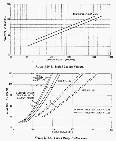
Design scaling employed the latest techniques and materials which could be applied to missile design immediately. By employing advanced techniques and materials a missile of 36 inches diameter could approach the performance of the nominal 60-inch diameter 21 percent missile. Therefore a detailed layout was also made of a 36-inch diameter 21 percent missile.
This smaller size could reduce missile cost, increase the number of missiles which carried by a particular aircraft, and minimize the handling, stowage, and launching problems.
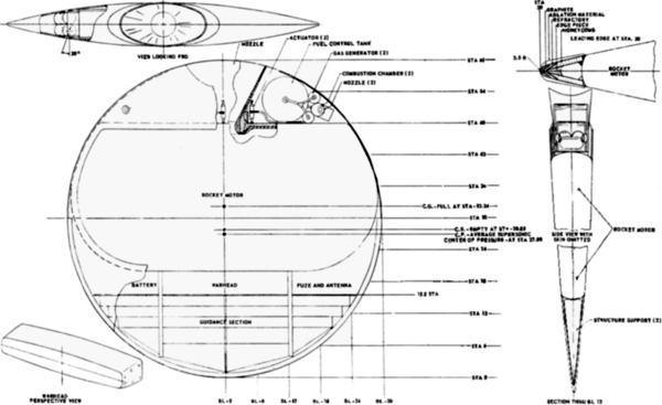
60-Inch Diameter 21 Percent Missile
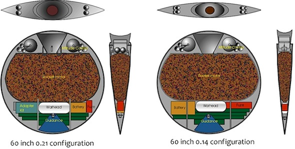
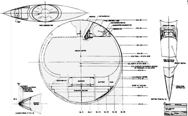
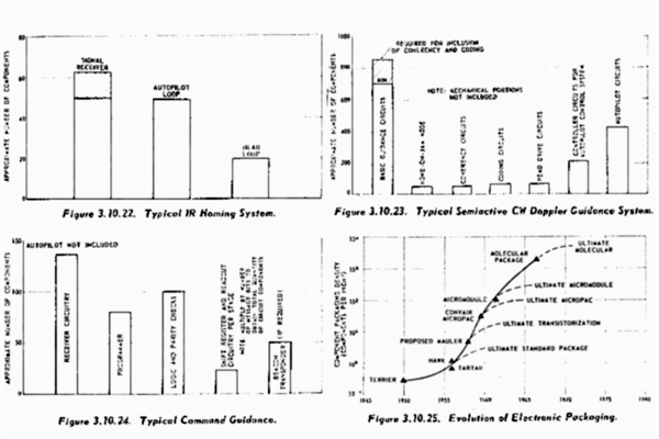
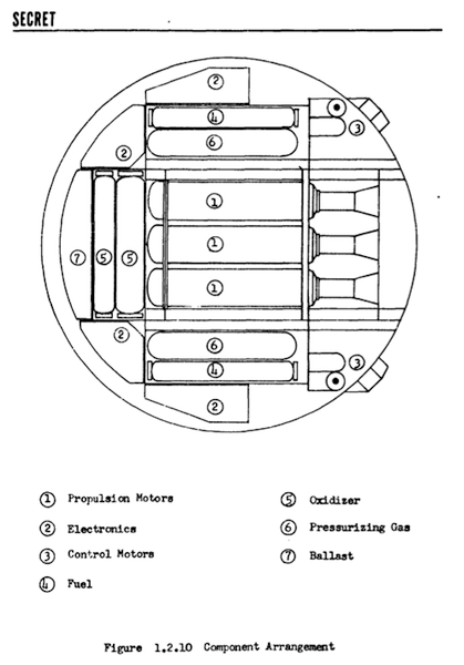
The electronics section, consisting of the guidance, autopilot, fuze, adaption kit (when a nuclear warhead was employed), and power supply, was in the thin forward end of the missile. Two structural beams extended from the leading edge to the rocket motor forward bulkhead to provide aeroelastic body stiffening and attachments for mounting electronic packages.
A detailed study was conducted in future trends for electronic components that showed the increased future capability possible.
Interchangeable nuclear or shaped-charge conventional high explosive warheads would be suspended between the two forward beams. It was determined that a nuclear warhead would be available during the Pye Wacket development time period which could be adapted to the 21 percent missile.
The integral rocket motor for the nominal configurations was a pancake type of basic thick skin construction. The solid propellant motor burned at 250 PSI chamber pressure. This thick skin utilized a honeycomb or waffle type construction. This resulted in reduced structural weight and increased strength since the external skin of the rocket motor formed an integral part of the missile aerodynamic surface.
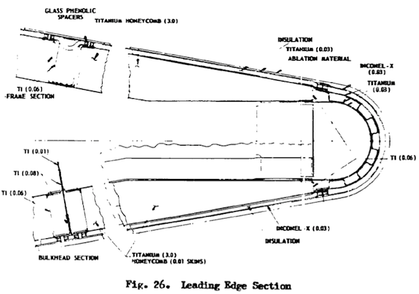
The leading edge consisted of laminated construction. Over the steel edge joint an insulating material was attached which supported the actual leading edge of carbon. The entire section was covered by ablation materials. This leading edge extended over the forward 180 deg of periphery of the missile. The edge around the remaining aft portion of the missile was constructed of honeycomb material in the same manner as the skin.
The reaction control system was packaged in the aft end of the missile on both sides of the main nozzle. These reaction controls operated by means of four fixed nozzles which exhausted through the top and bottom aft surfaces. Pitch, yaw, and roll control were obtained by differential throttling of the propellant flow to the four fixed combustion chambers.
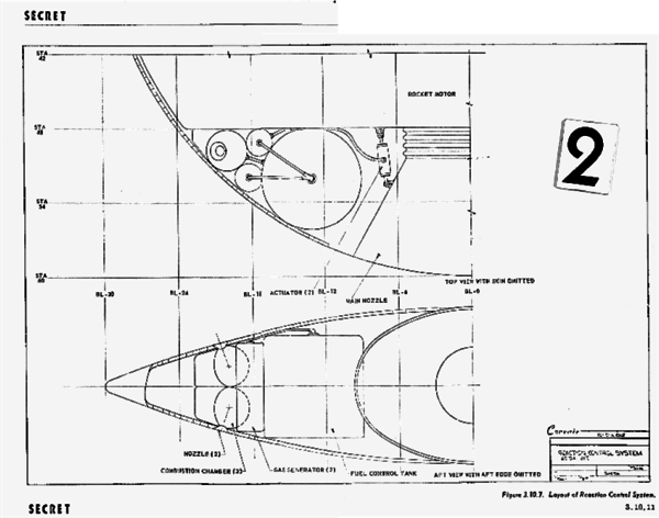
The entire reaction force system including propellant, pressurizing charge, servos, and thrust chambers would be constructed as an integral package for installation into either side. Electrical signals to control propellant flow were transmitted from the autopilot in the electronics section to the aft section via electrical harnesses inside the periphery of the missile.
The main motor swivel nozzle with 10 deg of action in both pitch and yaw provided additional control forces during the boost phase of flight. A final design might need thrust vector control in one plane. Mass injection could be substituted for nozzle swiveling. Openings in the top and bottom skins over the nozzle exit region allowed the nozzle to extend outside the missile contour when deflected in the pitch plane.
Electrical connection to the launcher and location of the umbilical connector would depend on final design of the launch mechanism. Obviously the originally-planned center-threaded hole might be difficult in the pancake motor design.
The missile skin could be easily removed in two major sections by disconnecting a main joint across the forward edge of the rocket motor. This allowed easy access to all components for assembly, test, checkout and servicing. To insure reasonable skin temperatures the entire external surface was covered by an ablative material of varying thickness as required by aerodynamic heating considerations.
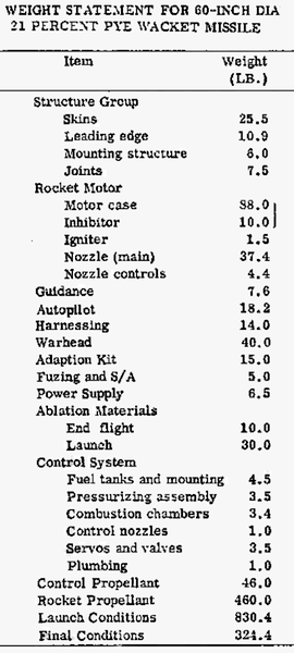
The 60-inch diameter 21 percent thickness ratio missile had a launch weight of 530.4 pounds and an empty weight of 324.4 pounds.
60-Inch Diameter 14 Percent Missile
The 60-inch 14 percent missile was less capable due to the lower missile mass.
36-Inch Diameter 21 Percent Missile
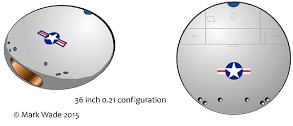
A feasibility design was conducted on a smaller 36-inch Pye Wacket missile. A 21 percent thickness-to-diameter ratio was chosen to facilitate component packaging while affording the greatest reduction of diameter. The simplified fuze was an active fixed angle type which optimized the fuzing problem for maximum kill probability. The fuze package and the guidance package would be encapsulated and electronically shielded by means of direct deposition of metallic film. The safe and arm mechanism provided positive safing under all conditions of shipment and handling. Arming could not occur until the missile had experienced the proper boost acceleration in the proper direction for a specified length of time.
The warhead was centrally located between the forward rocket motor bulkhead and the guidance package. Warhead support was furnished by attachment to the forward mounting beams. A nuclear warhead as favored by Eglin could not be accomodated in the small volume available in the 36 inch design. Instead a 20-pound controlled fragmentation warhead which fit the missile contour and employed flat aft and front surfaces was chosen.
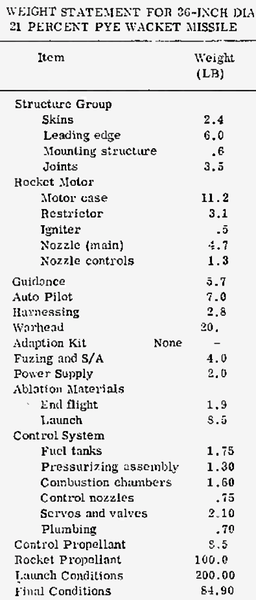
A pancake type solid propellant rocket motor and a reaction control system similar to those for the 6O-inch diameter missile were assumed.
To better illustrate the packaging arrangement of the 36-inch diameter missile a conceptual mockup was constructed.
Other Applications
Omnidirectional launch and excellent performance characteristics made manned-aircraft defense the most promising application for Pye Wacket. However Pye Wacket could also be a game-changing all-purpose air-to-air and surface-to-air missile. Interceptor aircraft could launch Pye Wackets simultaneously against multiple targets in a dispersed formation of oncoming bombers at ranges of up to 40 miles and altitudes of up to 120,000 feet. Use of Pye Wacket as an air-to-surface tactical weapon would allow aircraft to attack targets far from the line of flight at extremely large offset ranges. Air-to-air ranges were based on attacking air targets at the same altitude as the launch aircraft with the missile still at Mach 2. Therefore supersonic ground impact points well in excess of these distances were possible with Pye Wacket.
The Pye Wacket configuration would also provide an ideal manned spacecraft. Pye Wacket would function as a blunt body for re-entry when at an angle of attack of 90 deg. Following the maximum phase of heating and deceleration it would pitch over and provide a high lift body at small angles.
Development Plan
It would not be possible to proceed with a production design without a great deal of additional analysis and laboratory testing leading to flight test of a prototype. The acquisition of experimental aerodynamic data for design purposes had barely begun. Lift, drag and stability information had to be obtained from low speed to the hypersonic range. Yaw data was needed in the entire range from 0 to 180 degrees with a simulated jet-on condition. Much work was needed to develop a stable launching system that provided sufficient ejection velocity. Interactions between the propulsion system, basic structure, and the thermal protection required thorough investigation to establish a compatible group of solutions. The tradeoff between technical maturity, development time, cost, reliability, logistics, and operations had to be considered prior to determining whether the propulsion system should use solid or packaged liquid propellants. Testing of structural models would be necessary to establish the dynamic and static characteristics. These results in turn might affect the rocket motor operating pressure and motor performance.
Ablative materials and methods of applying these to the basic structure had to be analyzed and verified by experimentation. Solving fabrication and application of refractory materials to the leading edge of the vehicle required solutions. Aeroelastic investigations were necessary to enable the establishment of dynamic structural performance limits.
The development of a workable control system that provided artificial stability would be fundamental to the success of the Pye Wacket concept. Work to establish acceptable reaction jet time constants was needed. Wind tunnel studies were necessary to study interaction of the jets with airflow and the best reaction jet orientation.
Flight testing would be mandatory to demonstrate stabilized controllable flight by means of a reaction jet control system and omnidirectional launch capability. Off-the-shelf components would allow the concept to be proven and refined prior to committing to a production design. It was proposed that a series of ground-launched vehicles would be used to test basic vehicle performance and stabilization. This would be followed by three lots of missiles fired from a supersonic rocket sled to verify and refine the omni-directional launch capability.
Pye Wacket Phase II
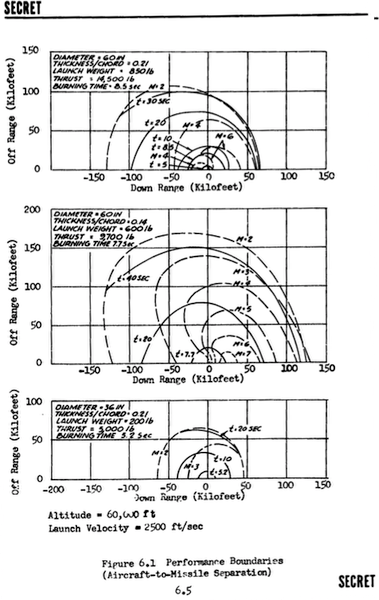
In line with the recommendations of the first report, the next year was spent designing a Feasibility Test Vehicle (FTV). The three-volume, 595 page result was completed on 15 February 1961. The FTV was a version of the 60-inch design that could be could be fabricated in a short time with off-the-shelf components and existing solid rocket motors for launch by rocket sled
Aerodynamic data obtained during 80 hours of wind tunnel testing at Arnold Engineering Development Center, Tullahoma, Tennessee used two heavily instrumented 1/3-scale models. One was instrumented to measure forces and moments and the other to measure the body pressure distributions.
The pressure model simulated the pitch and roll reaction control jets with cold gas at chamber pressures ranging from 100 to 1000 psia. The models were tested at Mach numbers ranging from 0.6 to 5.0, at angles of attack from 0 to 15 degrees and at sideslip angles from 0 to 180 degrees.
The reaction control system was studied extensively with special attention on obtaining the high thrust level with the required response time. Reaction control studies culminated in the requirement for a 500-pound thrust level and a 5 millisecond response time. Existing systems had neither the thrust levels or response time required for the FTV. A Convair company-sponsored test program of the response obtainable with an existing 300-pound thrust motor identified the development work required to meet FTV requirements. These tests, together with the results of an industry survey, indicated development of a system for the FTV in a short period would not be difficult.
The aerodynamic test data allowed a definitive structural design to be made. Together with the reaction control system studies, this then allowed a detailed simulation of the stabilization and control system for the missile.
The resulting autopilot had to fully exploit the unique properties of this configuration using a nonlinear control philosophy. The aerodynamic moments were of such a magnitude that four control motors would be required for pitch and and four for roll. The autopilot was studied primarily in forward, crosswind and aft launch conditions. Autopilot parameters were verified on a time varying three-dimensional simulation.
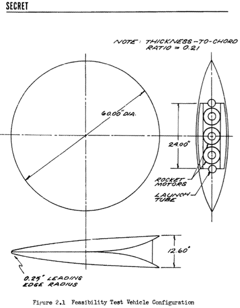
The resulting Pye Wacket Feasibility Test Vehicle design was 60 inches in diameter with a 21% thickness-to-chord ratio. The maximum thickness of 12.6 inches occurred at the blunted trailing edge. The main propulsion was provided by three M58A2 rocket motors. The M58A2 was in production for the Falcon missile, was readily available, and had demonstrated a high degree of reliability. These motors would boost the FTV from the rocket sled speed of 550 mph to over Mach 2.
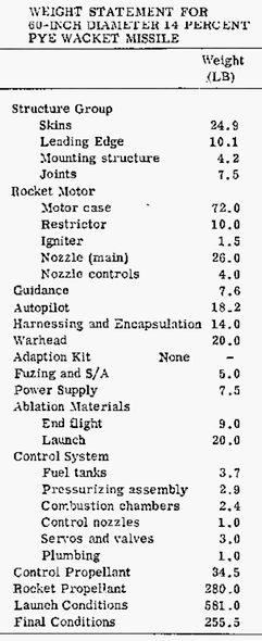
FTV Weight Summary
Structure: 66 lbs
Reaction Control Propellant System: 37 lbs
Reaction Control Propellant: 35 lbs at launch, 18 remaining at burnout
Reaction Control Motors: 30 lbs
Electronics: 40 lbs
Booster motors: 137 lbs at launch, 42 lbs at burnout
Miscellaneous: 11 lbs
Ballast: 69 lbs
Total: 425 lbs at launch, 313 lbs at burnout, 295 lbs empty
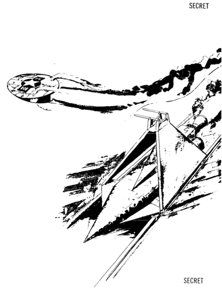
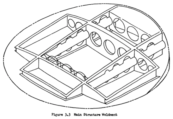
The main structure weldment of the Feasibility Test Vehicle was four magnesium alloy (AZ 31B) channels criss-crossing the missile planform. This weldment, when coupled with the missile skin, provided structural rigidity in all planes. The launcher tubes and booster support were an integral part of the weldment in order to ensure maximum alignment. The cast magnesium-alloy skin could be removed to allow access to all components for easy assembly, checkout and servicing.
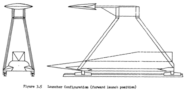
The launcher was a twin-rail system capable of 360 degree rotation in the horizontal plane and 90 degrees in the vertical plane. The launcher rails slid into two longitudinal cylinders on either side of the booster motors. The launcher design incorporated sufficient ground clearance to allow at a 100% safety margin beyond the predicted missile "drop-off" during aft launch.
Pye Wacket Phase III
The Phase II report recommended authorization of a Phase III flight test program to demonstrate proof of the basic concept. Convair proposed fabrication and flight test of 12 FTV's from a high speed sled. In addition to proof-of-concept, the flight test program would provide important data on transients encountered at launch in maneuver, and test the non-linear autopilot and high response reaction control system.
The first six months of the Phase III effort would concentrate on development and proof-testing of the autopilot and reaction control system. At the same time fabrication drawings for the FTV and test sled would be produced based on the Phase II configuration studies. Following fabrication, flight tests would be conducted using the high speed sled at the Edwards Flight Test Center Facility (the Hurricane Mesa Facility mentioned in some earlier Pye Wacket accounts had already been shut down). Flights from the sled would be made for forward, side, and aft-launch conditions. Photographic coverage would be obtained as well as data from the missile telemetering system and ground surveillance.
A further recommendation was that the USAF issue a specific requirement for a weapon which could exploit the inherent advantages of the Pye Wacket concept. This would expedite development of the weapon and advance its operational availability date.
Although some have speculated that at this point Pye Wacket went black and was in fact developed, by the time Phase II was completed in February 1961 the United States had a new President, John Kennedy, and a new Secretary of Defense, Robert McNamara. McNamara, accountant, formerly and briefly head of Ford Motor Company, proceeded to cancel every single innovative defense program in sight. High speed bombers and interceptors, nuclear-powered aircraft, missiles, and spacecraft, all were axed or scaled back to low-cost study efforts. Active bomber defense was dumped. The accountant's approach was to use existing B-52's for low-altitude penetration under the radar while waiting (and waiting) for the F-111. In this environment it is doubtful that Pye Wacket hardware advanced beyond the end of the Phase II study.
It was not quite the end, however... things were afoot in the black world after all...
The Manned Anti-Satellite System
The USAF had the SAINT (Satellite Inspector for Space Defense) anti-satellite system under study since June 1958 and had awarded the development contract to RCA for a three-phase Saint I unmanned program covering the Green Saint and White Saint inspection and satellite destruction spacecraft. Studies were also underway on Blue Saint, a Saint II follow-on manned vehicle.
Blue Saint was seen as competing with the well-advanced Boeing X-20 Dynasoar manned glider program, and in October 1961 it was criticized by a USAF panel for over-optimistic schedule and budget. All of this was heavily classified. It is not known if there was a competitive bidding for Blue Saint, or if Convair submitted a proposal. It seems that Martin Aircraft was the winner, as it was connected with the related public experimental SV-5, X-23, and X-24 lifting body spacecraft in the early 1960's. Another player was McDonnell Aircraft, who was beginning work leading to the Isinglass reconnaissance spacecraft in 1965.
Against this turbulent background Earl Honeywell suddenly emerged in public at the Eighth Symposium on Ballistic Missile and Space Technology in San Diego on 17 October 1963 to describe in considerable detail Convair's ultimate derivative of Pye Wacket, the Manned Anti-Satellite System. This looks like it may have been Convair's losing proposal for Saint II. Making it public was rather remarkable given the deep black nature of Saint. However McNamara had essentially cancelled Saint in October 1962 and it is possible that there was no longer any prohibition in discussing it. Or it may have been deliberate misinformation, to hide the fact that behind the cancellation of Saint was a move to the deeper-black air-launched Isinglass program. For whatever reason, Honeywell was careful to note that his paper "...was the result of General Dynamics/ Pomona-funded research and in no way can be construed as having the endorsement of the Department of Defense or the U.S. Air Force". That research had begun during Pye Wacket Phase II, with the first report issued in March 1961, only a month after the FTV report.
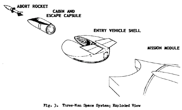
The Manned Vehicle (MV) was designed for launch by the same man-rated Titan III launch vehicle in development for the Dyna Soar. The approach was that the MV would stand off at a safe fifty-mile distance from the target satellite while a small Interspector/Killer (I/K) device would rendezvous with the target, examine it up close, then destroy it on command if needed. This approach allowed the MV and the I/K devices to have very large delta-V capabilities (7000 feet/second for the MV and 9600 ft/sec for the I/K). This would allow a quick response. Any satellite could be intercepted within 100 minutes with launch at almost any time. Alternatively multiple satellites in varying orbits could be intercepted on a single mission. This was in contrast to coplanar schemes like Saint I or the Soviet IS-A ASAT, which had to be launched into the orbital plane of the target. Their limited maneuverability meant tight once- or twice-daily launch windows. The scheme also allowed the crew to remain at a safe distance from the hostile satellite. Soviet military satellites were in fact equipped with self-destruct charges, although it is not known if US intelligence was aware of this.
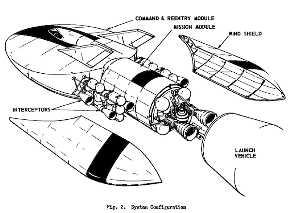
The MV in orbit had two modules. Weight breakdown was as follows:
Command Module (CM): 8,500 lbMission Module (MM): 20,500 lb consisting of:
Four Inspector/Killer Devices (I/K): 1,680 lb
Engine: 3,600 lb
Propellant: 14,300 lb
Control, Radar, Misc.: 920 lb
Total: 29,000 lb
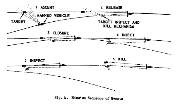
The baseline mission involved a minimum energy scenario. During Phase 1 the MV ascended to the target satellite orbit and the radar was in search mode. In Phase 2 the MV radar acquired the target while the MV neared apogee 50 miles ahead of the target. At this time an I/K Device would be released and allowed to coast freely along the ascent trajectory. In Phase 3 the manned vehicle reached apogee and injected into the target orbit. The inspector meanwhile was in the slower transfer trajectory. Inspection was initiated when the target came within range and the inspector made an orbit plane correction if required. In Phase 4 the target caught up with the inspector which then injected into the target orbit. In Phase 5 the inspector maneuvered around the target to perform close inspection. In Phase 6, if the target was determined to be hostile, the target would be destroyed. Phase 6 could also be implemented at any time after the I/K was released from the manned vehicle.
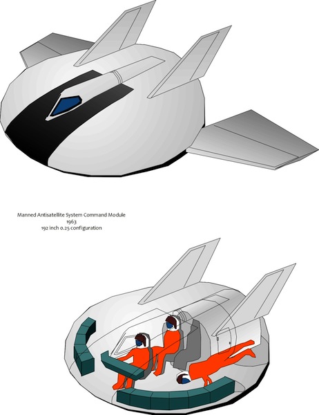
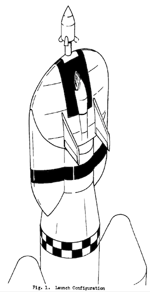
The CM was a lenticular reentry vehicle with a crew of three based on Pye Wacket work. The this was the only module of the system that returned to earth. The cockpit section could be separated from the command module at subsonic speeds for abort on the launch pad, during the initial phases of ascent, or in case of difficulties in landing.
The CM would reenter at a 60 to 75 deg angle of attack, presenting a thin blunt surface which was optimum for deceleration at higher altitudes. Trajectory control woud be by rolling while still maintaining the high angle of attack. The lenticular vehicle minimized heat shield requirements while providing a high hypersonic L/D ratio, maximizing cross range capability. Once the saucer slowed down to transonic speed, horizontal stabilizers were deployed.
The 16-foot-diameter CM would have been rather cramped. The thickness of the saucer is not indicated, but even with the cockpit section above the top of the saucer, the cockpit could not have had a height much greater than five feet and the saucer thickness had to be greater than the 21% maximum considered for Pye Wacket. How the deployable wings, and landing gear or skids were housed is not clear. One crew member at a time could work their way from the cockpit module through a small hatch into a claustrophobic pressurized cabin which at least allowed them to stand up while working. The 8500 pound estimated mass of the densely-packed vehicle seems optimistic compared to the 13,000 pounds of the Apollo command module.
The CM used a double-wall structure. The inner wall of deep-cored honeycomb sandwich panels was the load-bearing structure. The outer wall heat shield consisted of segmented laminate panels of ablative material, radiative metal skin, and insulation material. To handle thermal expansion during reentry the overlapping panels were attached to the inner wall with flexible thermally insulated clips.
The MM Mission Module consisted of four satellite inspector/killer mechanisms the fire control radar, and the propulsion system for orbital maneuvers. This propulsion system is not described in detail, but appears to be a smaller-diameter version of the Titan Transtage with about half the propellant load.
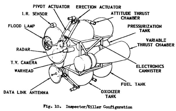
The I/K devices had two main engines of 1600 lbs thrust each and six separate attitude control engines of 5 lbs thrust each. Aside from the propellant and pressurization tanks, the device carried a data link antenna, target tracking radar antenna, TV camera, IR sensor, warhead, and a flood lamp for inspection while in the earth's shadow. The radar and data link antenna were folded for minimum storage volume in the mission module. The I/K device fit in a volume of 47 in. by 38 in. by 38 in. when packaged in the launch configuration.
The I/K's two gyro-stabilized antennas tracked the target and the MV simultaneously. The guidance system used these two positions to keep the device oriented horizontally between the MV and the target.
Optical inspection of the target would be accomplished by the MV using telescopes. In the earth's shadow the I/K device would illuminate the target. Any necessary detailed assessment would be made by a fly-around of the target by the I/K using television, infrared, and radiation sensors. Commands to the I/K and data from it would be relayed via a PCM/FM data link.
The I/K semi-active seeker was a pulse receiver compatible with the fire control radar on the manned vehicle. A home-on-jam mode was also be provided. If the target took evasive maneuvers, the I/K would fly a modified proportional navigation course to intercept. The I/K's shaped charge fragmenting warhead had a theoretical kill probability of 95.3% for a 2-square-foot target with an aiming error of 10 ft.
The I/K propellant was nitrogen tetroxide / 50% hydrazine - 50% unsymmetrical dimethyel hydrazine. The 3200 lb thrust provided a 12 G acceleration. Packaging requirements required the use of two chambers with a 30:1 nozzle area ratio and two sets of propellant tanks. Total weight of each I/K was 473 pounds, of which 290 lbs was propellant. Electronics, the communication link, and inspection system took up 48 pounds, the warhead 38 pounds, the dry mass of the propulsion system 96 pounds, with only 8 pounds for the light-weight structure.
The highest priority target would be an enemy orbital bomber. This was not a fantasy; such spacecraft were under study and development in both countries. This would require sensors for nuclear bomb detection; target mass determination; multispectral electromagnetic radiation detection. A decoy exterminator function would be necessary in case an orbital bomber went into action. None of these capabilities was included in the initial design, but could be developed in the future.
In one scenario ferret equipment could be fitted on the I/K to allow it to monitor enemy communications. It would loiter near the target and proceed with destruction only when the target received an order from the ground to initiate hostile operations. It was also possible that some "clever device" could be installed on the I/K to reveal and destroy decoys without requiring the firing of the warhead.
After Pye Wacket
After the 17 May 1963 appearance Earl Honeywell disappears completely from the documentary record. No further papers have been declassified to date that appear with his name or that of the elusive D R Geise. Public records show that he continued to live in the Pomona area, probably continuing to work for General Dynamics. His wife passed away on 7 October 1969, and he remarried on 5 February 1971. Sometime before 1993 he returned to the Seattle, Washington area. He died there on 9 October 1998 and was buried at Tahoma National Cemetery. On the other hand Hatalsky and Velton had well-documented careers and continued at General Dynamics Pomona until retirement.
Did Earl Honeywell continue his work on deep black programs? Or was Pye Wacket the young engineer's biggest project? Was he, like Orson Welles, someone who lived his life in reverse, with the biggest accomplishment being followed by decades of mundane work?
Active air-to-air bomber defenses never were never developed further. Radar evasion, stealth, decoys, air-to-surface missiles, and electronic countermeasures were used instead.
On the other hand it is known is that the Air Force continued to pursue manned spaceflight on behalf of the CIA. By 1964 there were competing designs for an air-launched manned reconnaissance spacecraft by General Dynamics Fort Worth and McDonnell Saint Louis. It is possible Earl Honeywell was involved with the Convair project. However the nod seems to have gone to McDonnell, who pursued development of Isinglass until 1968. Officially, neither of these concepts were found to have advantages in comparison to satellites to justify the high development and operating risk and costs.
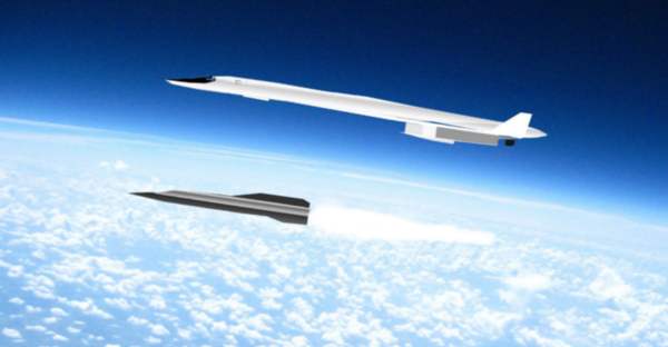
Then in March 2006 Aviation Week and Space Technology made the astounding claim that the United States had developed a reusable two-stage-two-orbit manned spacecraft in the 1990's, dubbed Blackstar, and flown it on numerous orbital and suborbital missions. Development began after the Challenger shuttle disaster in 1986 and the Blackstar was only retired in 2005. If this system actually existed and was flown, the history of manned spaceflight would have to be revised.
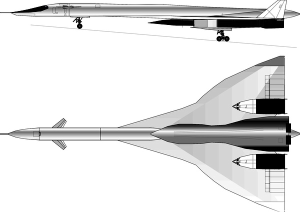
The first stage of the Blackstar system was said to be a Mach 3+ winged air-breathing first stage evidently developed from North American's XB-70 bomber. The second stage was the XOV manned eXperimental Orbital Vehicle lifting body. The system was developed by a "consortium of US aerospace companies" at the behest of an "unspecified US government agency". The system was so classified that it remained unknown to the nation's top military and civilian space planners, while they labored to design, but never developed, an equivalent white-world system. Blackstar was designed to handle numerous missions: strategic reconnaissance; anti-satellite; quick-reaction small satellite launch; and delivery of small conventional warheads.
Did Blackstar exist? Did Earl Honeywell and the mysterious D R Geise have black-world careers building Pye Wacket derivatives? We may never know.
References and Chronology
1958: Experimental and Theoretical Investigations on Lenticular Rocket Shapes (U) Technical Planning Group, Directorate of Development, Air Proving Ground Center, Eglin Air Force Base, Florida (SECRET) Leading edge deflection was proposed by the Air Proving Ground Center and was investigated in this APGC "in house" test program.26 November 1958: R&D EXHIBIT NO. PGEM 58-162 Research Requirements ofr Lenticular Rocket, Technical Planning Group, Directorate of Development, Air Proving Ground Center, Eglin Air Force Base, Florida.
23 March 1959: RFP to Industry
April 1959: CPC-1393 Proposal for Lenticular Rocket Feasibility Study, presented to Air Proving Ground Center, United States Air Force by Convair- Pomona, April 1959.
June 1959: ARDC Project 3811 Contract: AF 08(635)-542 six month study Phase I
23 June 1959: Honeywell, E. E., TM-334-337, "Compilation of Power-Off Base Drag Data and Empirical Methods for Predicting Power-Off Base Drag, Convair-Pomona, 23 June 1959.
Honeywell, E. E., Giese, D. J., TM-334-375 Pye Wacket Wind Tunnel Test No. I Pre-Test Report, " by E. E. Honeywell and D. J. Giese, Convair-Pomona July 1959.
Honeywell, E. E., Giese, D. J., TM-334-385 and TM-334-3S5A, "Pye Wacket Wind Tunnel Test No. II Pre-Test Report, , Convair-Pomona, September 1959.
September 1959: Velton, E. J. and Hatalsky, W., IC-334-231 Visit to Convair Scientific Research Division, Convair, A Division of General Dynamics, Pomona, California, September 1959.
October 1959: Velton, E. J. and Hatalsky, W., IC-334-248 "Trip Report on Consultation with Dr. A. J. Eggers at Ames Laboratory, Moffet Field, California, Convair, A Division of General Dynamics, Pomona, California, October 1959.
November 1959: Honeywell, E. E., Giese, D. J. , TM-334-409 Preliminary Results of Pye Wacket Wind Tunnel Tests, Convair Pomona, November 1959
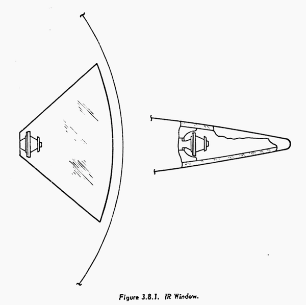
December 1959: TM349-15 Preliminary Investigation of Aerodynamic Heating Effects on an Infrared Window, Convair-Pomona, December 1959.
14 January 1960: Pye Wacket Lenticular Rocket Feasibility Study, Convair Division of General Dynamics Corporation for the Air Proving Ground, Air Research and Development Command United States Air Force, Eglin Air Force Base, Florida, 14 January 1960. ARDC Project 3811 Contract: AF 08(635)-542
March 1960: Infrared Study Summary and Conclusions, Volume V-A, Crosley Report No. 6654-58-ll(V-A), Contract No. AF 33 (616)-5311. Crosley contract for guidance and control.
May 1960: DD613 North American Aviation Defense Study, ; Project 5155, May 1960. Documented evaluation of passive and active defense systems for B-70.
May 1960: Pye Wacket Lenticular Rocket Feasibility Study AFSC- TF-60-25, May 1960, Secret. Published version of February Feasibility Study.
July 1960: Giese, D. J., TM 334-450 Pye Wacket Wind Tunnel Test No. III- PWT Pre-Test Report, Convair-Pomona, July 1960.
July 1960: Giese, D. J., TM-334-454, Pye Wacket Wind Tunnel Test No. IV, Pre-Test Report, Type A Wind Tunnel, Convair-Pomona, July 1960.
July 1960: Jones, R. D., and Featherstone, H. A., TM-334-451, "Estimated Omnidirectional Launch Aerodynamic for-PY WACKET FTV Configuration, Convair-Pomona, July 1960.
12-23 September 1960: Tests of a 1/3-scale Pye Wacket missile conducted in the PWT 16-Foot Transonic Circuit for the Convair Division of General Dynamics Corporation.
December 1960: Baker, D. C. and Galigher, L. L., INVESTIGATION OF STATIC STABILITY AND AERODYNAMIC EFFECTS OF CONTROL JETS ON A 1/3-SCALE Pye Wacket MISSILE AT TRANSONIC MACH NUMBERS, PWT, ARO, Inc., December 1960.
22 December 1960: Convair/Pomona Letter No. II-8837/2217 dated 22 December 1960 to Directorate of Procurement, Eglin AFB, Florida Phase III of the Feasibility Studies Proposal - involved fabrication of a number of flight vehicles and flight test of these missiles from a high speed sled (12 vehicles proposed).
15 February 1961: Pye Wacket Feasibility Test Vehicle Study, General Dynamics Pomona, California, for Detachment 4, Headquarters, Air Force Systems Command, Eglin Air Force Base, Florida, 15 February 1961. AFSC Project 3811 Contract AF 08(635)-1168.
March 1961: Honeywell, E. E., TM-341-147:,Manned Re-entry Vehicle Preliminary Design Study, General Dynamics/Pomona, March 1961.
October 1961: DEVELOPMENT OF AIRBORNE ARMAMENT 1910-1961; VOLUME II BOMBER DEFENSE, AFSC HISTORICAL PUBLICATIONS SERIES 61-52-(2) , Air Force Systems Command, October 1961. Discuses Lenticular Defense Missile for B-70 in 1959.
October 1962: Honeywell, E. E., ERR-PO-086 Preliminary Design of a Three Man Orbital and Re-entry Vehicle, General Dynamics/Pomona, October 1962
January 1963: Honeywell, E E, Satellite Inspector/Killer Mechanism Study, General Dynamics/Pomona, TM-341-177, January 1963.
17 October 1963, "Anti-Satellite System Proposed", The San Mateo Times
16-18 October 1963: Honeywell, E. E., "MANNED ANTI-SATELLITE SYSTEM", General Dynamics Corporation, Pomona Division, Pomona, California, in TRANSACTIONS OF THE EIGHTH SYMPOSIUM ON BALLISTIC MISSILE AND SPACE TECHNOLOGY, VOLUME II, Held at the United States Naval Training Center San Diego, California on 16-18 October 1963
Also consulted:
McPhee, John, The Curve of Binding Energy: A Journey into the Awesome and Alarming World of Theodore B. Taylor, Farrar, Straus and Giroux,1994
Dyson, George, Project Orion - The True Story of the Atomic Spaceship, Henry Holt and Company, 2002.
Jenkins, Dennis R and Landis, Tony R, Valkyrie: North American's Mach 3 Superbomber, Specialty Press, 2004
Scott, William B, "Two-Stage-to-Orbit 'Blackstar' System Shelved at Groom Lake?", Aviation Week and Space Techonology, 6 March 2006
More at: Pye Wacket.
Back to top of page
Home - Search - Browse - Alphabetic Index: 0- 1- 2- 3- 4- 5- 6- 7- 8- 9
A- B- C- D- E- F- G- H- I- J- K- L- M- N- O- P- Q- R- S- T- U- V- W- X- Y- Z
© 1997-2019 Mark Wade - Contact
© / Conditions for Use